Foldable display panel

a display panel and foldable technology, applied in the field of display technologies, can solve the problems of increasing the need for 3 m*n pixels, increasing the stress concentration of the film layer, and increasing the external tensile force and pressure of the bending area of the tft, so as to improve the ability of the sub-pixel to be located, improve the quality of the product, and ensure the reliability of the display device.

Active Publication Date: 2020-12-15
WUHAN CHINA STAR OPTOELECTRONICS SEMICON DISPLAY TECH CO LTD
View PDF8 Cites 0 Cited by
  • Summary
  • Abstract
  • Description
  • Claims
  • Application Information

AI Technical Summary

Benefits of technology

[0007]In view of the above, the present disclosure provides a foldable display panel to solve the problem of stress concentration of the diagonal corners or protrusion of the sub-pixels located in the bending area, the technical problem of electroluminescent layer or film encapsulation layer falling off in the bending area is improved.
[0018]In comparison with the prior art, the foldable display panel of the embodiments of the disclosure enhance the ability of the sub-pixel located in the foldable area to withstand stress during bending process by using an elliptical or curved quadrilateral sub-pixel pattern located in the foldable area. It prevents detachment of electroluminescence and the encapsulation film layer in the foldable area. Thereby a reliability of a display device is ensured and a quality of a product is improved.

Problems solved by technology

But the disadvantage is that when one wants to make a m*n display, a total of 3 m*n pixels needs to be made.
However, in an actual folding process of products, film layers of the bending area of the TFT are subjected to external tensile force and pressure much more than those of the non-bending area.
When a bending portion crosses the diagonal of the square of the sub-pixel, diagonal corners of the square sub-pixel tend to be subjected to stress concentration, and it is prone to cause an electro-luminescence (EL) layer or thin film encapsulation (TFE) layer therein to fall off.
Therefore, the prior art has drawbacks and is in urgent need of improvement.

Method used


Image

  • Foldable display panel
  • Foldable display panel

Examples


Embodiment Construction

[0023]The following description of the embodiments is provided by reference to the following drawings and illustrates the specific embodiments of the present disclosure. Directional terms mentioned in the present disclosure, such as “up,”“down,”“top,”“bottom,”“forward,”“backward,”“left,”“right,”“inside,”“outside,”“side,”“peripheral,”“central,”“horizontal,”“peripheral,”“vertical,”“longitudinal,”“axial,”“radial,”“uppermost” or “lowermost,” etc., are merely indicated the direction of the drawings. Therefore, the directional terms are used for illustrating and understanding of the application rather than limiting thereof.

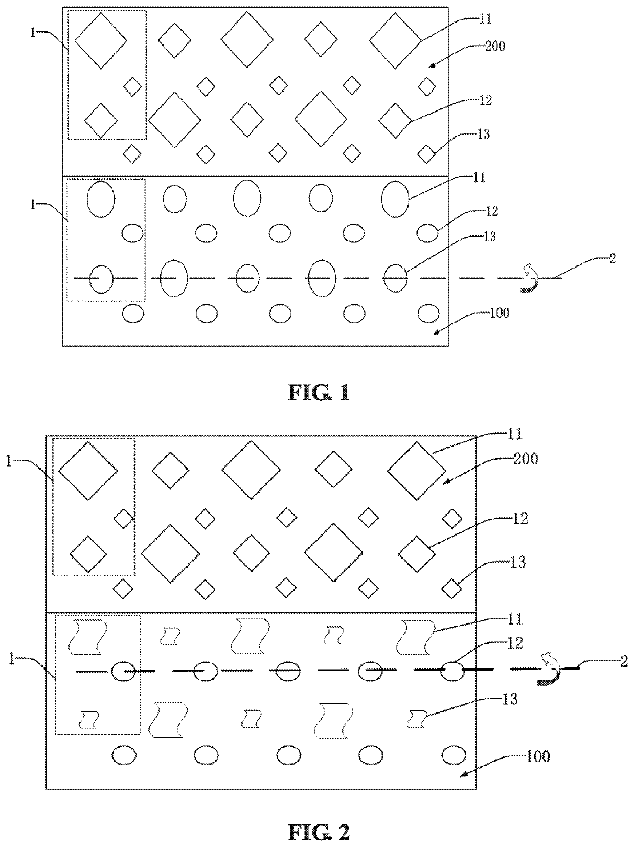
[0024]One embodiment of the present disclosure provides a foldable display panel. It will be described separately as follows. Referring to FIGS. 1, and 2, one embodiment of the disclosure provides a foldable display panel including a foldable area 100 and two non-foldable areas 200. The foldable display panel further includes at least two pixel units 1. The pixel units ...


PUM

PropertyMeasurementUnit
widthaaaaaaaaaa
stress concentrationaaaaaaaaaa
shapeaaaaaaaaaa

Abstract

A foldable display panel is provided. The foldable display panel includes a foldable area and two non-foldable areas. The foldable display panel further includes at least two pixel units. Each of the pixel units includes three sub-pixels. A pattern of the sub-pixel in the foldable area is elliptical or is curved quadrilateral. A pattern of the sub-pixel in the non-foldable area is a rhombus. An ability of the sub-pixels located in the foldable area 100 to withstand stress during a bending process is enhanced. Detachment of an electroluminescent layer or a thin film encapsulation layer located in the foldable area is prevented, thereby a reliability of a display device is ensured and a quality of the product is improved.

Description

FIELD OF INVENTION[0001]The present disclosure relates to display technologies, and more particularly to a foldable display panel.BACKGROUND OF INVENTION[0002]A display panel is composed of many pixels, and in order for each individual pixel to display a variety of colors, each pixel needs to be divided into red, green and blue sub-pixels. That is to say, the three sub-pixels constitute a whole pixel, that is, a color pixel. When it is necessary to display different colors, the three sub-pixels respectively emit light with different brightness, and because a surface area of the sub-pixel is very small, it is visually mixed into a desired color. A sub-pixel arrangement is arranged in red, green, blue (RGB) arrangement, pixel arrangement (PenTile), and diamond arrangement.[0003]The RGB arrangement is the most standard arrangement. It divides a square pixel into three equal parts, each of which is given a different color, so that a color pixel can be formed. In fact, most liquid crysta...

Claims


Application Information

Patent Timeline
Patent Type & Authority Patents(United States)
IPC IPC(8): H01L27/00H01L27/32H01L51/00
CPCH01L27/3246H01L27/3283H01L51/0097H01L27/3218H01L2251/5338G09F9/301G09F9/33G09F9/35Y02E10/549H10K59/352H10K59/353H10K2102/311H10K59/122H10K59/173H10K77/111
Inventor ZHAO, JINRONG
Owner WUHAN CHINA STAR OPTOELECTRONICS SEMICON DISPLAY TECH CO LTD
Why Eureka
Try Eureka