Wirebonding for side-packaged optical engine

a side-packaged, optical engine technology, applied in the direction of electrical appliances, basic electric elements, instruments, etc., can solve the problem of combining light to or from optoelectronic components into fiber optic cabling

Active Publication Date: 2020-12-29
REFLEX PHOTONICS
View PDF21 Cites 0 Cited by
  • Summary
  • Abstract
  • Description
  • Claims
  • Application Information

AI Technical Summary

Problems solved by technology

However, it may be challenging to couple light to or from the optoelectronic components into the fiber optic cabling due to the physical and / or geometric restrictions imposed by the setup.

Method used


Image

  • Wirebonding for side-packaged optical engine
  • Wirebonding for side-packaged optical engine
  • Wirebonding for side-packaged optical engine

Examples


Embodiment Construction

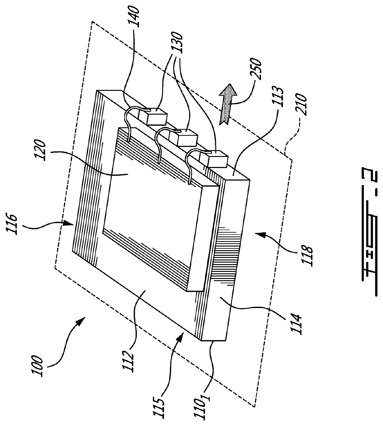
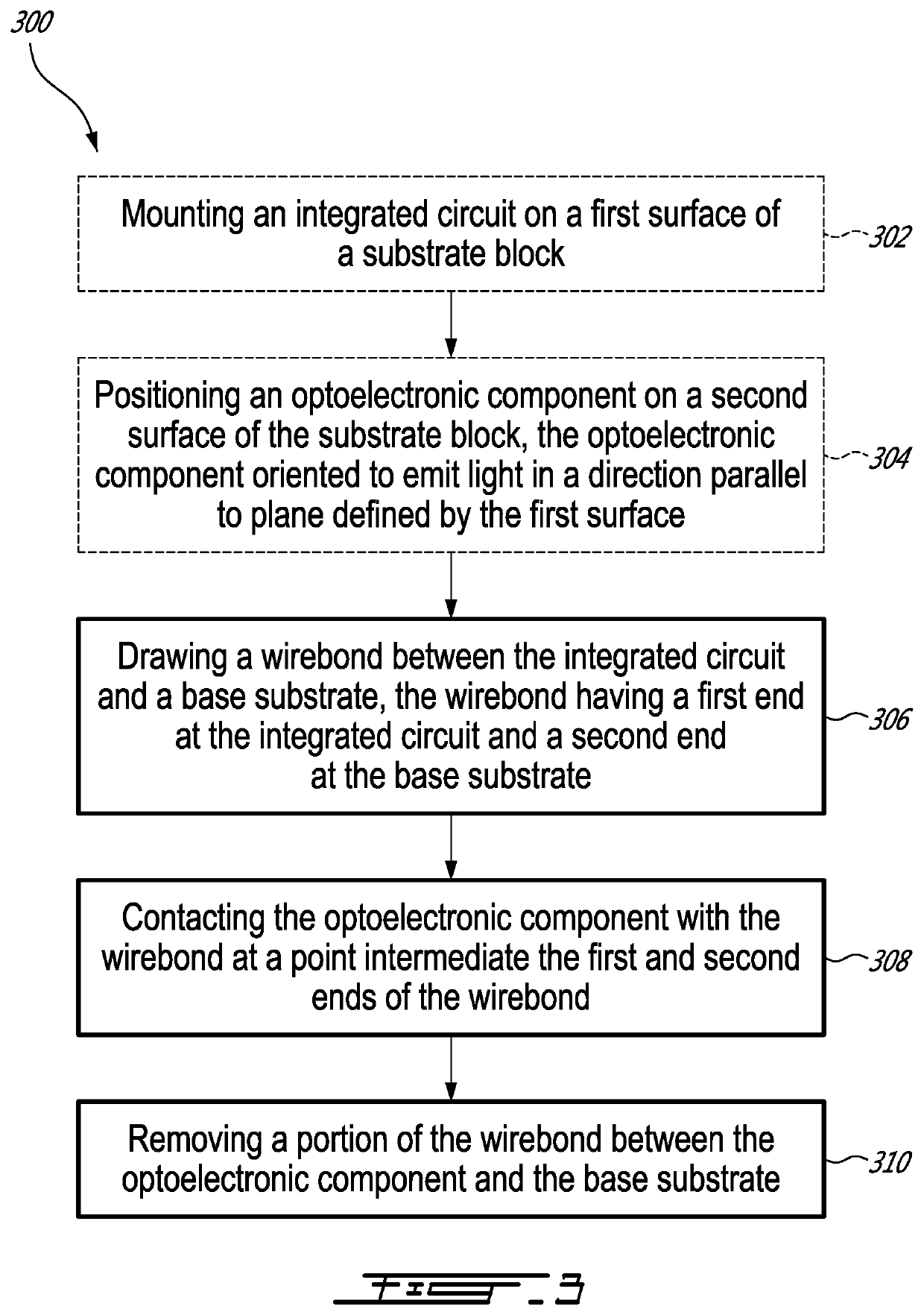
[0032]There is described herein a method for connecting an integrated circuit and an optoelectronic component using wirebonding. In the prior art, the method can involve a very complicated kinematic, gimbaled mount inside a wirebonding machine where the part is rotated and moved between the first and second bond attach. Instead, there is described herein a simplified, two-step method. The method comprises having one or more wirebonds fully attached in one plane, and then the entire part is re-placed in a second orientation so that a bond-and-cut operation on the wirebond can be made by attaching a new portion of the wirebond to a new location on the second plane. This is followed by a third action to remove the unrequired portion of the wirebond.

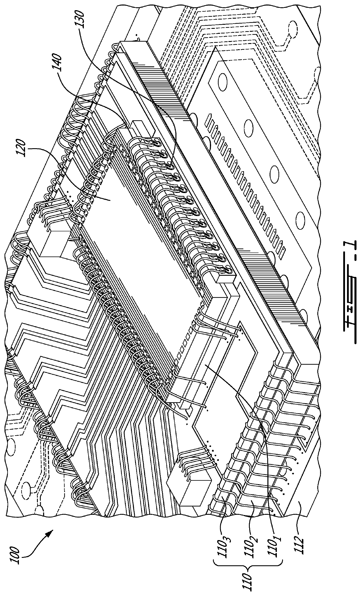
[0033]With reference to FIG. 1, there is shown an optical engine 100 configured to produce laser light, for example a laser-based optical signal. The optical engine 100 comprises at least one substrate block 110, an integrated circuit 120, a...


PUM

PropertyMeasurementUnit
angleaaaaaaaaaa
angleaaaaaaaaaa
angleaaaaaaaaaa

Abstract

The present disclosure is drawn to wirebonding for optical engines having side-mounted optoelectronic components. An integrated circuit is mounted on a first surface of a substrate block, and an optoelectronic component is positioned on a second surface of the substrate block and is oriented to emit light in a direction parallel to a plane defined by the first surface. A wirebond is drawn between the integrated circuit and a base substrate on which the substrate block is mounted. A optoelectronic component is then contacted with the wirebond, and a portion of the wirebond between the optoelectronic component and the base substrate is removed.

Description

CROSS-REFERENCE TO RELATED APPLICATIONS[0001]This patent application claims priority of U.S. provisional Application Ser. No. 62 / 463,347, filed on Feb. 24, 2017.TECHNICAL FIELD[0002]The present disclosure relates to laser-light producing or detecting devices, and more specifically to the wirebonding of laser or detector components in laser-light producing or detecting devices.BACKGROUND OF THE ART[0003]Optical communication relies on the ability to generate, transmit, and detect light-based signals. Modern optical communication, performed via fiber optics, uses modulated laser-based signals to transmit information. The laser-based signals are produced by optical engines, and then transmitted over a network of fiber optic cabling. The laser-based signals can then be modulated, amplified, and ultimately detected via suitable hardware and software components.[0004]To build an optical engine using semiconductor technology, an integrated circuit is mounted on a substrate, such as a print...

Claims


Application Information

Patent Timeline
Patent Type & Authority Patents(United States)
IPC IPC(8): H01L23/00G02B6/42
CPCG02B6/4292G02B6/4249H01L24/06G02B6/428H01L2224/4809G02B6/3885G02B6/4274H01K5/00
Inventor ROLSTON, DAVID ROBERT CAMERON
Owner REFLEX PHOTONICS
Why Eureka
Try Eureka