
Busbar component, terminal block, and vehicular device

a technology for busbar components and terminal blocks, applied in the field of busbars, can solve problems such as affecting the waterproofness of o-rings

Active Publication Date: 2020-12-29
YAZAKI CORP
View PDF16 Cites 0 Cited by
  • Summary
  • Abstract
  • Description
  • Claims
  • Application Information

AI Technical Summary

Benefits of technology

The busbar component described in this patent reduces the play of the holder, allowing it to make direct contact with the O-ring when the busbar is pushed. This results in better waterproof performance for the attached member and ensures necessary protection. The invention provides a solution for improving the connection between a wire harness and a terminal block in vehicles.

Problems solved by technology

If the holder 7 is in contact with the O-ring 5 in a state that the holder 7 is bent to some extent due to its play, a problem arises that this affects the waterproofness of the O-ring 5.

Method used


Image

  • Busbar component, terminal block, and vehicular device
  • Busbar component, terminal block, and vehicular device
  • Busbar component, terminal block, and vehicular device

Examples


embodiment

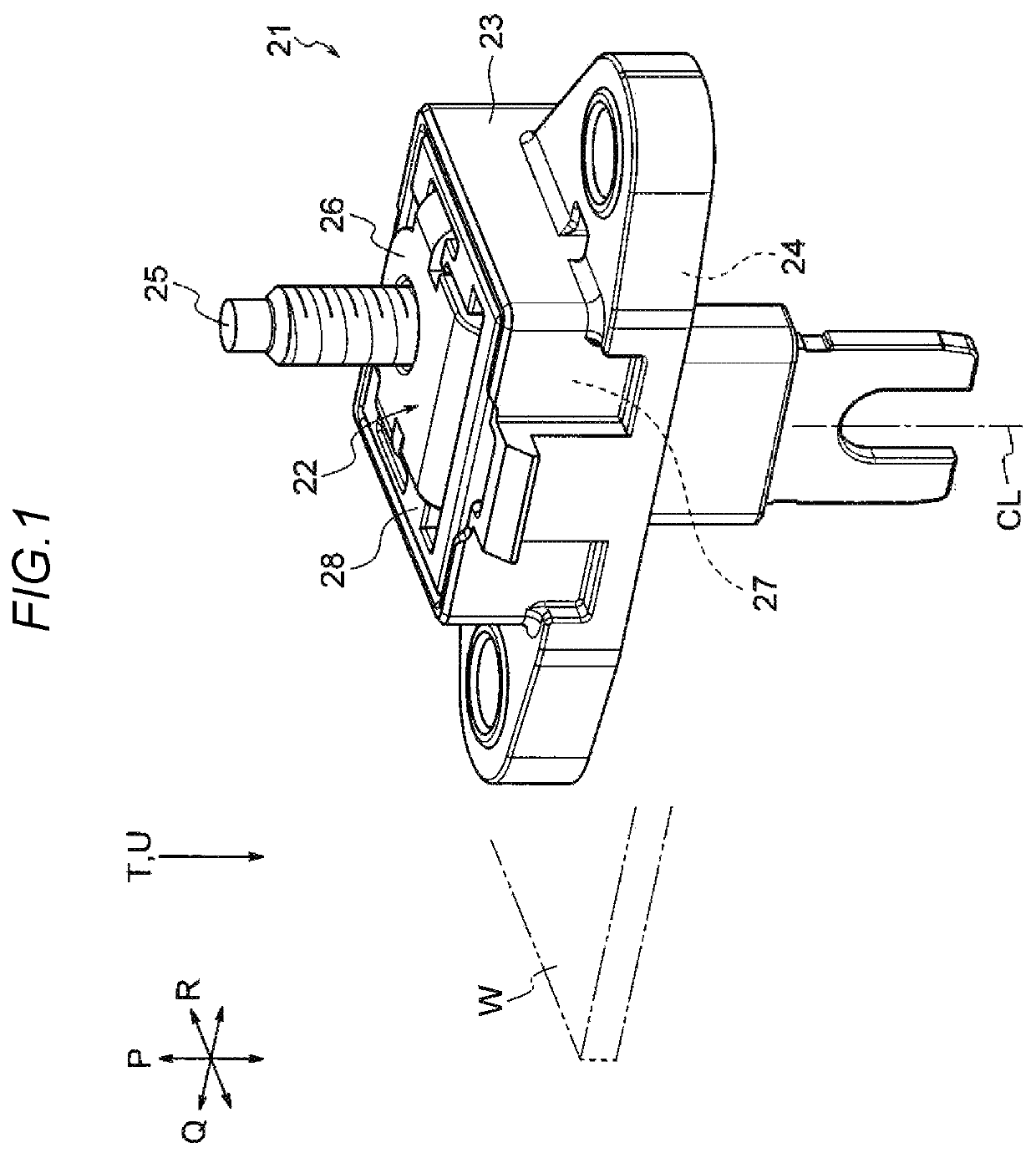
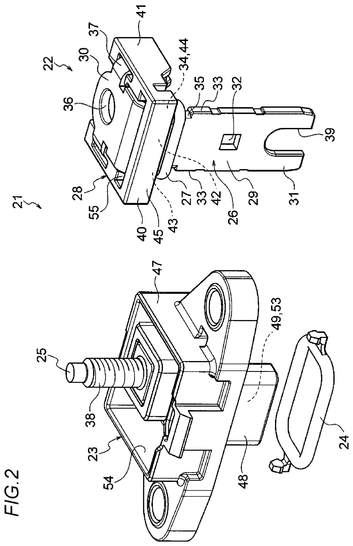
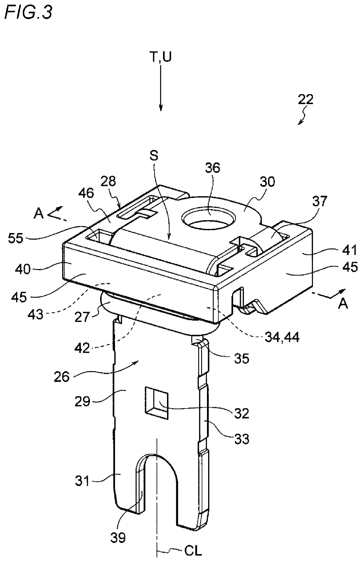
[0046]An embodiment of the present invention will be hereinafter described with reference to the drawings. FIG. 1 is a perspective view showing a busbar component 22 and a terminal block 21 according to the embodiment. FIG. 2 is an exploded perspective view of the terminal block 21. FIG. 3 is a perspective view of the busbar component 22. FIG. 4 is an exploded perspective view of the busbar component 22. FIG. 5 is perspective view of the busbar component 22 and is partially a sectional view taken along line A-A in FIG. 3. FIGS. 6A-6D show the structure of a busbar 26. FIGS. 7A and 7B show the structure of a holder 28. FIGS. 8A and 8B show the structure of a housing 23. FIG. 9 shows a halfway state of attachment of the busbar component 22 to the housing 23. FIG. 10 shows a state that the attachment of the busbar component 22 to the housing 23 is completed. FIG. 11 is an enlarged view of an essential part of FIG. 10.

[0047]In the embodiment, arrows P, Q, and R shown in FIG. 1, for exam...


PUM


Abstract

A busbar component constructing a terminal block has a busbar, a circular O-ring attached to a busbar main body of the busbar, and a holder attached to the busbar main body through an insertion hole of the holder. The busbar main body is formed with a busbar-side engagement portion. A holder main body is arranged between a busbar-side engagement portion and the O-ring. The holder main body is formed with a ring-shaped pressing portion on one opening side of the insertion hole. The holder main body is formed with, on another opening side of the insertion hole, a holder-side engagement portion which is engaged with the busbar-side engagement portion.

Description

CROSS-REFERENCE TO RELATED APPLICATIONS[0001]This application is based on and claims priority under 35 USC 119 from Japanese Patent Application No. 2018-66896 filed on Mar. 30, 2018, the contents of which are incorporated herein by reference.TECHNICAL FIELD[0002]The present invention relates to a busbar component having a busbar, an O-ring, and a holder. The invention also relates to a terminal block which includes the busbar component as well as to a vehicular device to which a wire harness is connected via the terminal block.BACKGROUND ART[0003]A terminal block disclosed in Patent document 1 is known which is attached to a wall of a device box and used for electrical connection between the inside and the outside of the wall. The configuration of this terminal block will be described below briefly with reference to FIGS. 12 and 13. A terminal block 1 is equipped with a housing 2, a busbar 3, a stud bolt 4, O-rings 5 and 6, and a holder 7.[0004]The housing 2, which is attached to a ...

Claims


Application Information

Patent Timeline
Patent Type & Authority Patents(United States)
IPC IPC(8): H01R13/52B60R16/023B60R16/02H01R9/24H01R13/41H01R13/516H01R13/74H01R25/16
CPCH01R13/41H01R13/521H01R13/748B60R16/0207H01R9/24H01R13/5202H01R13/516H01R25/162B60R16/0239H01R2201/26
Inventor KAWAMURA, YUKIHIROISAKA, NAOKI
Owner YAZAKI CORP
Learn More