Method for encoding a light field content

a technology of light field and content, applied in the field of computation imaging, lightfield acquisition devices, plenoptic cameras, can solve the problems of large content to be stored, 4d light field, and light field technology cannot live besides regular 2d or 3d imaging

Active Publication Date: 2020-12-29
INTERDIGITAL VC HLDG INC
View PDF31 Cites 0 Cited by
  • Summary
  • Abstract
  • Description
  • Claims
  • Application Information

AI Technical Summary

Problems solved by technology

However, due to the fact that plenoptic devices are extremely heterogeneous (for example we can distinguish plenoptic devices of type 1 or 2 (which define particular optical arrangements of the micro-lenses (for example micro-lenses with different focal lengths, etc.))), and that camera arrays come in different flavors, it appears that all these light field acquisition devices have their proprietary file format, so that light-field technology cannot live besides regular 2D or 3D imaging as there is no standard supporting the acquisition and transmission of multi-dimensional information.
However, one drawback of this representation of a 4D light-field is that content to be stored is huge as mentioned in p.

Method used


Image

  • Method for encoding a light field content
  • Method for encoding a light field content
  • Method for encoding a light field content

Examples


Embodiment Construction

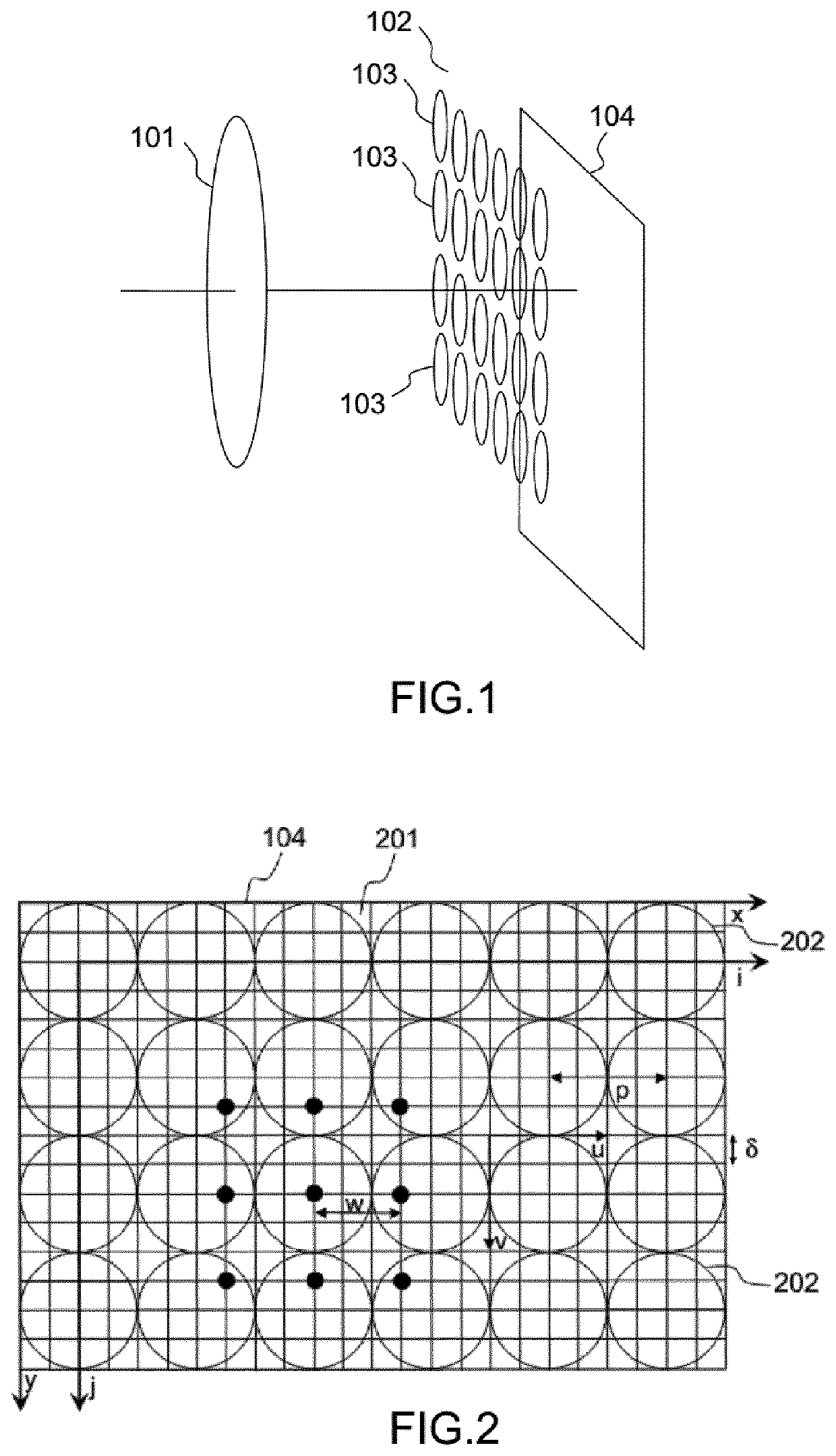
lass="d_n">[0149]FIG. 1 present schematically the main components comprised in a plenoptic camera. More precisely, a plenoptic camera comprises a main lens referenced 101, and a sensor array (i.e. an array of pixels), referenced 104. Between the main lens 101 and the sensor array 104, a microlens array referenced 102, that comprises a set of micro lenses referenced 103, is positioned. It should be noted that optionally some spacers might be located between the micro-lens array around each lens and the sensor to prevent light from one lens to overlap with the light of other lenses at the sensor side. Hence, a plenoptic camera can be viewed as a conventional camera plus a micro-lens array set just in front of the sensor as illustrated in FIG. 1. The light rays passing through a micro-lens cover a part of the sensor array that records the radiance of these light rays. The recording by this part of the sensor defines a micro-lens image.

[0150]FIG. 2 present another view of the sensor arr...


PUM


Abstract

In one embodiment, it is proposed a method for encoding a light field content. The method is remarkable in that it comprises: —obtaining, for a set of light rays (401) associated with said light field content, four coordinates per light ray from a two planes parametrization (2000; 402, 403) of said light field content; —obtaining (2001), for each light ray from said set, two coordinates from said four coordinates, corresponding to a projection of said light rays from said set onto a plane (404, 405, P) perpendicular to two planes used in said two planes parametrization, defining points in a first 2D ray diagram (Π(χ1, χ2), Π(χ1, χ2)); —applying (2002) a discrete Radon transform on said first 2D ray diagram (Π(χ1, χ2), Π(χ1, χ2)) that delivers lines of interest in said first 2D ray diagram; —encoding (2003) said lines of interest into encoded lines of interest; and—storing (2004) said encoded lines of interest.

Description

[0001]This application claims the benefit, under 35 U.S.C. § 365 of International Application PCT / EP2016 / 071873, filed Sep. 15, 2016, which was published in accordance with PCT Article 21(2) on Mar. 23, 2017, in English, and which claims the benefit of European Patent Application No. 15306437.3, filed Sep. 17, 2015, European Patent Application No. 15306439.9, filed Sep. 17, 2015, European Patent Application No. 15306440.7, filed Sep. 17, 2015, European Patent Application No. 15306441.5, filed Sep. 17, 2015, European Patent Application No. 15306435.7, filed Sep. 17, 2015 and European Patent Application No. 15306438.1, filed Sep. 17, 2015.TECHNICAL FIELD[0002]The disclosure relates to the field of computational imaging, light-field acquisition devices, and plenoptic cameras. More precisely, it deals with a representation format for the light-field that can be used for transmission, rendering, processing, mixing of light-field data.BACKGROUND[0003]This section is intended to introduce ...

Claims


Application Information

Patent Timeline
Patent Type & Authority Patents(United States)
IPC IPC(8): G06K9/00G06T7/557H04N19/60H04N19/597
CPCH04N19/597H04N19/60G06T7/557G06T2207/10052
Inventor SEIFI, MOZHDEHDRAZIC, VALTERSCHUBERT, ARNOBURELLER, OLIVIER
Owner INTERDIGITAL VC HLDG INC
Why Eureka
Try Eureka