Electrical connection device for an electrical apparatus and connection method using said device

a technology of electrical equipment and connection device, which is applied in the direction of clamped/spring connection, etc., can solve the problems of insufficient solution, insufficient access to clamping screws, and inconvenient installation of accessories on the connection pad, etc., to save a large volume of space, convenient and fast implementation, and reliable and secure

Active Publication Date: 2021-01-12
SOCOMEC
View PDF4 Cites 0 Cited by
  • Summary
  • Abstract
  • Description
  • Claims
  • Application Information

AI Technical Summary

Benefits of technology

[0008]The present invention aims to overcome these drawbacks by proposing a novel connection device that is compact since it saves a large volume of space in electrical cabinets, ergonomic, operator-friendly, easy and fast to implement due to the small number of members to be screwed in place, versatile so as to be able to satisfy a plurality of connection configurations, multi-functional since it allows functionalities to be added, and reliable and secure thanks to automatic compensation of the clamping in the event of fatigue or vibrations.

Problems solved by technology

Moreover, this solution has numerous drawbacks.
The connection of each conductor in these accessories and the mounting of the accessories on each connection pad is tedious and time-consuming given the number of attachment screws that must be tightened.
It creates ergonomy issues regarding access to the clamping screws.
S50 26388 U proposes a solution allowing a main conductor and two lateral conductors parallel to one another to be connected to the same connection pad, by means of two attachment flanges arranged on either side of the connection pad and each provided with dedicated clamping screws, i.e. a total of three screws to be tightened for three conductors, which does not fully solve the problem posed.
This solution is attractive as regards the number of screws to be tightened, however it considerably complicates the placing of the conductors, which must be held in the connection device before and during the tightening of the single screw.
Chinese patents No 206 022 666 U and No 206 180 132 U disclose connection solutions with a limited number of conductors, which does not solve the problem posed.
To date, no ergonomic, operator-friendly and versatile solution exists for satisfying a wide range of connection configurations.

Method used


Image

  • Electrical connection device for an electrical apparatus and connection method using said device
  • Electrical connection device for an electrical apparatus and connection method using said device
  • Electrical connection device for an electrical apparatus and connection method using said device

Examples


Embodiment Construction

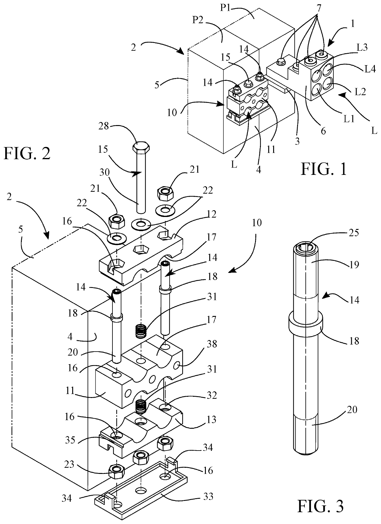
[0044]In the example embodiments shown, identical elements or parts bear the same reference numerals.

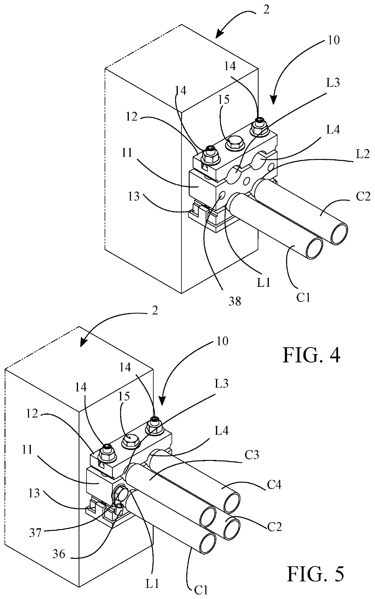
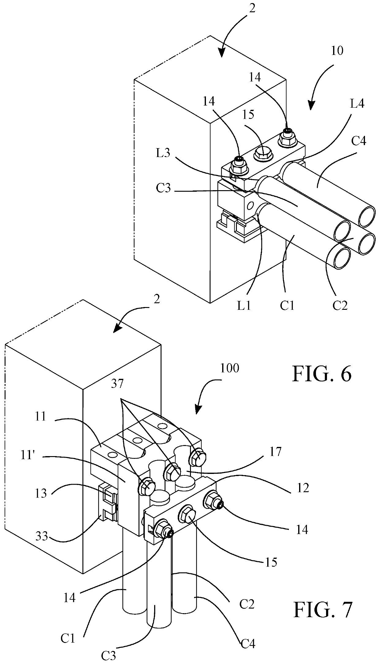
[0045]FIG. 1 very clearly illustrates the design differences between a connection device 1 according to the prior art and a connection device 10 according to the invention, and the results obtained, in particular in terms of ergonomics regarding accessing the attachment screws, operator-friendliness as regards the number of attachment screws to be screwed in place, and overall dimensions in an electrical cabinet (not shown), in accordance with the drawbacks of the prior art and the advantages of the invention described hereinabove. These two connection devices 1, 10 are shown side-by-side and each equip a pole P1, P2 of an electrical apparatus 2 of the switch or circuit breaker type, or any other electrical apparatus requiring a current supply. They each comprise four recesses L1, L2, L3, L3 (jointly or individually referred to as L) allowing four conductors C1, C2, C3, C4 (not shown...


PUM


Abstract

An electrical connection device for an electrical apparatus includes a connection pad and two attachment flanges arranged on either side of the connection pad. The attachment flanges and the connection pad include opposing cavities for delimiting four recesses capable of receiving at most four conductors. A pass-through clamping mechanism, formed by two lateral tie rods and a central rod, passes through the assembly constituted by superposition of the attachment flanges and the connection pad. The lateral tie rods include a support abutment arranged between the connection pad and one of the attachment flanges so that it is possible to differentiate the tightening, recess by recess, facilitating the placing of the conductors, the conductors being able to have different diameters.

Description

TECHNICAL FIELD[0001]The present invention relates to an electrical connection device for an electrical apparatus, this device comprising a connection pad and two attachment flanges, including an upper attachment flange and a lower attachment flange, arranged on either side of the connection pad and designed to attach at least one conductor to said connection pad.[0002]The invention further relates to a connection method for an electrical apparatus, wherein at least one conductor is clamped to a connection pad by means of an attachment flange.BACKGROUND ART[0003]Electrical apparatuses, such as, for example, switches, circuit breakers and similar apparatuses, comprise external connection pads, which are coupled to internal electrical contacts. The connection pads project from the housing of said apparatuses via faces, to allow the connection of conductors thereto ensuring a current supply and a current discharge. In a standard manner, the connection pads are flat and an attaching hol...

Claims


Application Information

Patent Timeline
Patent Type & Authority Patents(United States)
IPC IPC(8): H01R4/44H01R4/46
CPCH01R4/44H01R4/46
Inventor DUMONT, ROGER
Owner SOCOMEC
Why Eureka
Try Eureka