A heat shield device for hot isostatic pressing equipment

A technology of hot isostatic pressing and heat shield, which is applied in the field of static pressing equipment, can solve the problems of affecting the treatment effect of hot isostatic pressing, prolonging the heating time, increasing production costs, etc. Effect of high temperature resistance and improvement of heating capacity

Active Publication Date: 2022-02-11
钢研昊普科技有限公司 +1
View PDF0 Cites 0 Cited by
  • Summary
  • Abstract
  • Description
  • Claims
  • Application Information

AI Technical Summary

Problems solved by technology

When the heating rate inside the heat shield is too fast and the buoyancy generated in the heat shield exceeds the gravity of the heat shield itself, the inverted cup-shaped heat shield will float or tilt slightly. In order to ensure that the heat shield does not float up, maintain A lower heating rate, but a lower heating rate not only affects the effect of hot isostatic pressing, but also leads to a longer heating time and a longer overall production cycle of the equipment
At present, the domestic hot isostatic pressing equipment heat treatment market is in a stage of short supply, and the increase in production costs caused by prolonging the production cycle cannot be underestimated.

Method used


Image

  • A heat shield device for hot isostatic pressing equipment
  • A heat shield device for hot isostatic pressing equipment
  • A heat shield device for hot isostatic pressing equipment

Examples


Embodiment 1

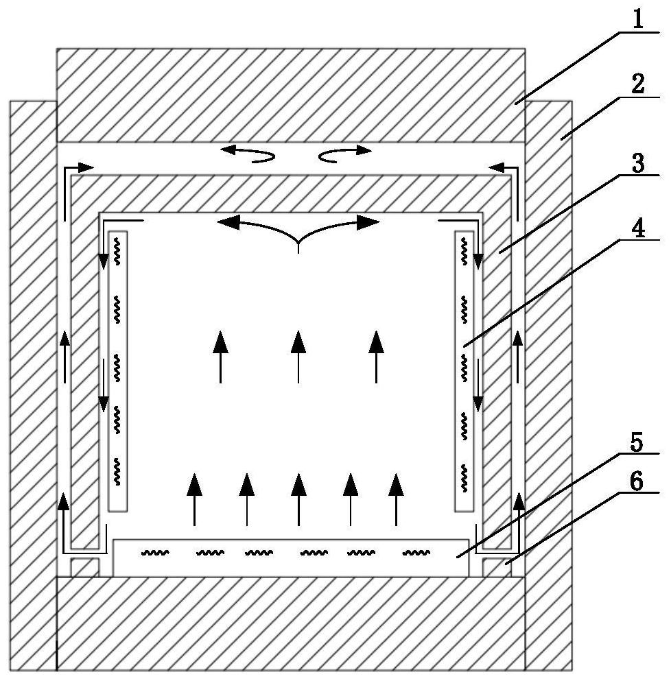
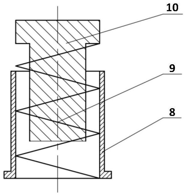
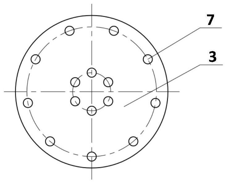
[0062] The invention provides a heat shield device for hot isostatic pressing equipment, which includes a heating body, a heat insulation layer, and a force transmission component. The heating element is a birdcage structure, with 30 tungsten-molybdenum alloy rings arranged radially, 56 tungsten-molybdenum alloy rods arranged axially, 4 layers of heat insulation layer, the outermost layer is made of stainless steel, and the inner 3 layers are molybdenum alloy layers. Granular or fibrous zirconia is filled between every two layers of the heat insulation layer. The force transmission part includes a spring 9 , a mounting seat 8 connecting the spring 9 and the heat shield 3 , and a support column 10 that increases the contact area between the spring 9 and the upper plug 1 . The schematic diagram of the positional relationship between the force transmission component 7 and the heat shield 3 is as follows: image 3 , the front view schematic diagram of the positional relationship ...

Embodiment 2

[0066] Embodiment 2 uses the same heat shield device as in Embodiment 1. The difference from Embodiment 1 is that the diameter of the heat shield applied to the RD1250 hot isostatic pressing equipment in Embodiment 2 is 1350mm, and its own weight is 2.2T. It is the largest when fully loaded. The heating rate is 4.8K / s. The distance between the heat shield and the upper plug is 90mm. Through measurement and calculation, considering the loss of elastic force of the spring after heating, it is necessary to apply a downward force of about 7.5KN to the heat shield to control the heat shield from floating up. Choose 110mm spring, 5 effective coils, 8mm spring wire diameter, and 70mm outer ring diameter. After calculation, a single set of force transmission parts at normal temperature and pressure can generate 674N for the heat shield, 14 sets of force transmission parts, and 6 sets of inner rings , 8 sets of outer rings, which can provide a downward force of about 9.4KN for the hea...


PUM

PropertyMeasurementUnit
lengthaaaaaaaaaa

Abstract

The invention relates to a heat shield device for hot isostatic pressing equipment, which belongs to the technical field of hot isostatic pressing equipment, and solves the problem that the heat shield of hot isostatic pressing equipment in the prior art has a small space volume and a small processing capacity per unit time And other issues. A heat shield device for hot isostatic pressing equipment, comprising a heating body, a heat insulating layer and a force conducting part; the heating body is arranged inside the heat shield; the heat insulating layer is arranged outside the heating body; the force conducting part is arranged The upper surface of the screen, the upper end surface of the force transmission part is in contact with the lower surface of the upper plug of the hot isostatic pressing device. The invention can increase the space volume of the heat shield, increase the processing capacity of the hot isostatic pressing device per unit time, and effectively ensure the stability of the hot isostatic pressing device and the controllability of the production process.

Description

technical field [0001] The invention relates to the technical field of hot isostatic pressing equipment, in particular to a heat shield device of hot isostatic pressing equipment. Background technique [0002] Due to its own process superiority, hot isostatic pressing technology is not only a special technology for powder metallurgy near net shape, but gradually expanded to multiple production fields such as casting densification treatment, dissimilar material connection and complex special-shaped parts manufacturing. Heat shields are thermal insulation devices in hot isostatic pressing equipment. Its main function has the following three points: (1) Its internal working space is kept warm through its own multi-layer insulation material; (2) The heating element structure is installed inside the heat shield, which is used to heat up the working space; (3) Insulation Multiple sets of temperature measuring devices are installed in different positions inside the heat screen to ...

Claims


Application Information

Patent Timeline
Patent Type & Authority Patents(China)
IPC IPC(8): B22F3/15
CPCB22F3/15B22F2003/153
Inventor 车立达陈硕莫寒胡雷李好峰石志敏翟一多刘元伟
Owner 钢研昊普科技有限公司
Why Eureka
Try Eureka