
Method for producing fiber composite components by means of a vacuum injection method

a vacuum injection and fiber composite technology, applied in the field of vacuum injection methods for fiber composite components, can solve the problems of high material cost, large quantity of expensive membrane materials, and high cost of materials, and achieve the effects of improving the static load capacity of the component, reducing the rejection rate, and improving the quality of the composite component produced with the separation material

Active Publication Date: 2021-01-26
FASERVERBUND INNOVATIONS UG HAFTUNGSBESCHRANKT
View PDF7 Cites 0 Cited by
  • Summary
  • Abstract
  • Description
  • Claims
  • Application Information

AI Technical Summary

Benefits of technology

[0014]The separation material can be a membrane of a flat, areal monolithic diffusion-open plastic material that comprises appropriate pores. The flat, areal plastic material can be produced in an extruder or can be cast and subsequently provided with the pores. A compacted nonwoven is also conceivable as a membrane. In addition to the plastic material or the nonwoven which can be produced and employed with great reliability, also other types of materials are conceivable as separation material, for example, also paper filters with a corresponding pore size and permeability. In case of paper filters, the properties can be adjusted beneficially by appropriate finishing, for example, impregnation or coating. The separation material is designed such that it enables breakthrough / passage of matrix material as soon as it has reached the separation material. The matrix material is thus not stopped by the separation material at any point in time but is only slowed down.
[0037]With the separation material according to the invention, it is also possible to convey in a targeted fashion a greater volume of the matrix material through the component chamber than required in order to produce the finished fiber composite component in the component chamber. The excess of matrix material which is sucked by means of the vacuum chamber through the separation material serves the purpose of achieving in the component chamber a uniform distribution of the matrix material while providing a fiber volume content as high as possible with a minimal proportion of gas bubbles in the matrix material of the finished fiber composite component. Since the separation material according to the invention is designed such that it significantly slows the passage of matrix material by means of the specified pore size but does not completely block its passage, the pressure differences are produced that enable the desired distribution of the matrix material in the component chamber and the removal of excess quantities of the matrix material.

Problems solved by technology

Because the membrane covers the component chamber and additionally at least a part of the entire tool in a flat arrangement, a very great quantity of the expensive membrane material is required.
Both of the afore described methods are comparatively expensive in regard to manufacturing fiber composite components because the employed membrane material is very expensive.
In order to configure the membrane material such that it is gas-permeable but impermeable to the matrix material, extremely small holes must be introduced into the membrane material which is correspondingly complex and causes high costs.

Method used


Image

  • Method for producing fiber composite components by means of a vacuum injection method

Examples


Embodiment Construction

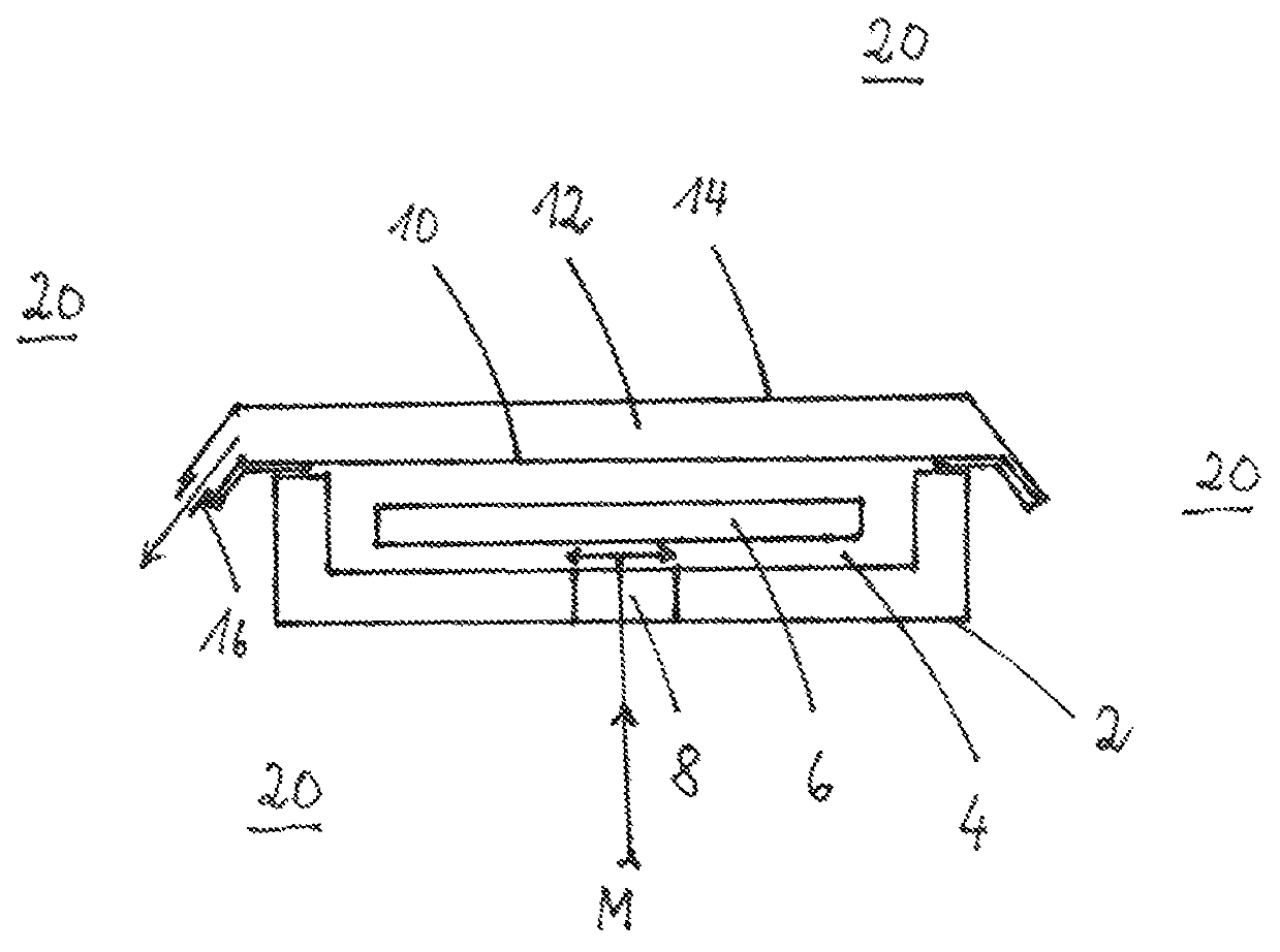
[0039]In order to explain the method of the invention, a purely schematic illustration of an embodiment of a tool 2 for use with the invention is provided. The tool 2 comprised a component chamber 4. A fiber composite semifinished product 6 is positioned in the component chamber 4. Through inlet 8 a matrix material M can be introduced into the component chamber 4, as indicated by the arrow. The separation material 10 according to the invention is placed sealingly on top of the component chamber 4. The separation material 10 provides a boundary relative to the vacuum chamber 12, i.e., separates the component chamber 4 from the vacuum chamber 12. The vacuum chamber 12 and the component chamber 4 are sealed by a gas-tight and matrix material-tight cover material 14 relative to the tool environment 20 and to the exterior. The cover material 14 is connected at least at the edges to the separation material (separation membrane) 10 such that no gas from the exterior, from the tool environm...


PUM

PropertyMeasurementUnit
pore sizeaaaaaaaaaa
pore sizeaaaaaaaaaa
viscosityaaaaaaaaaa

Abstract

In a method for producing a fiber composite component by vacuum injection, a fiber composite semifinished product is arranged in a component chamber of a tool. A vacuum chamber is arranged adjacent to the component chamber. The vacuum chamber is separated from the component chamber by a separation material. Component chamber and vacuum chamber are sealed relative to the tool environment by a gas-tight and matrix-material tight cover material. Vacuum is applied to the vacuum chamber and a matrix material is introduced into the component chamber. The matrix material is cured and the finished fiber composite component is removed from the component chamber. The separation material separating the vacuum chamber from the component chamber has a pore size between 0.4 μm and 30 μm and provides a matrix material-slowing action but is not matrix material-tight.

Description

BACKGROUND OF THE INVENTION[0001]The invention relates to a method for producing fiber composite components by means of a vacuum injection method, comprising the steps:[0002]arranging a fiber composite semifinished product in a component chamber of a tool,[0003]arranging and positioning a vacuum chamber for evacuating gas from the component chamber adjacent to the component chamber by means of a separation membrane separating the vacuum chamber from the component chamber,[0004]sealing the component chamber and the vacuum chamber relative to the tool environment by means of a gas-tight and matrix material-tight cover material,[0005]applying a vacuum to the vacuum chamber,[0006]introducing a matrix material into the component chamber, and[0007]curing and removing the finished fiber composite component.[0008]A corresponding manufacturing process is disclosed in US 2003 / 0011904 A1. The vacuum chamber is formed in accordance with the disclosed process method in that relative to the compo...

Claims


Application Information

Patent Timeline
Patent Type & Authority Patents(United States)
IPC IPC(8): B29C70/44B29C70/54
CPCB29C70/443B29C70/547B29C70/548B29C2791/006
Inventor DIERKES, DOMINIK
Owner FASERVERBUND INNOVATIONS UG HAFTUNGSBESCHRANKT
Learn More