
In-vehicle controller

a technology for vehicles and controllers, applied in the direction of electric control, gearing, machines/engines, etc., can solve the problems of low fluid viscosity and degraded controllability of lock-up clutches, and achieve the effect of prolonging the time for fuel cutting and ensuring the time for regenerating the filter

Active Publication Date: 2021-02-09
TOYOTA JIDOSHA KK
View PDF6 Cites 0 Cited by
  • Summary
  • Abstract
  • Description
  • Claims
  • Application Information

AI Technical Summary

Benefits of technology

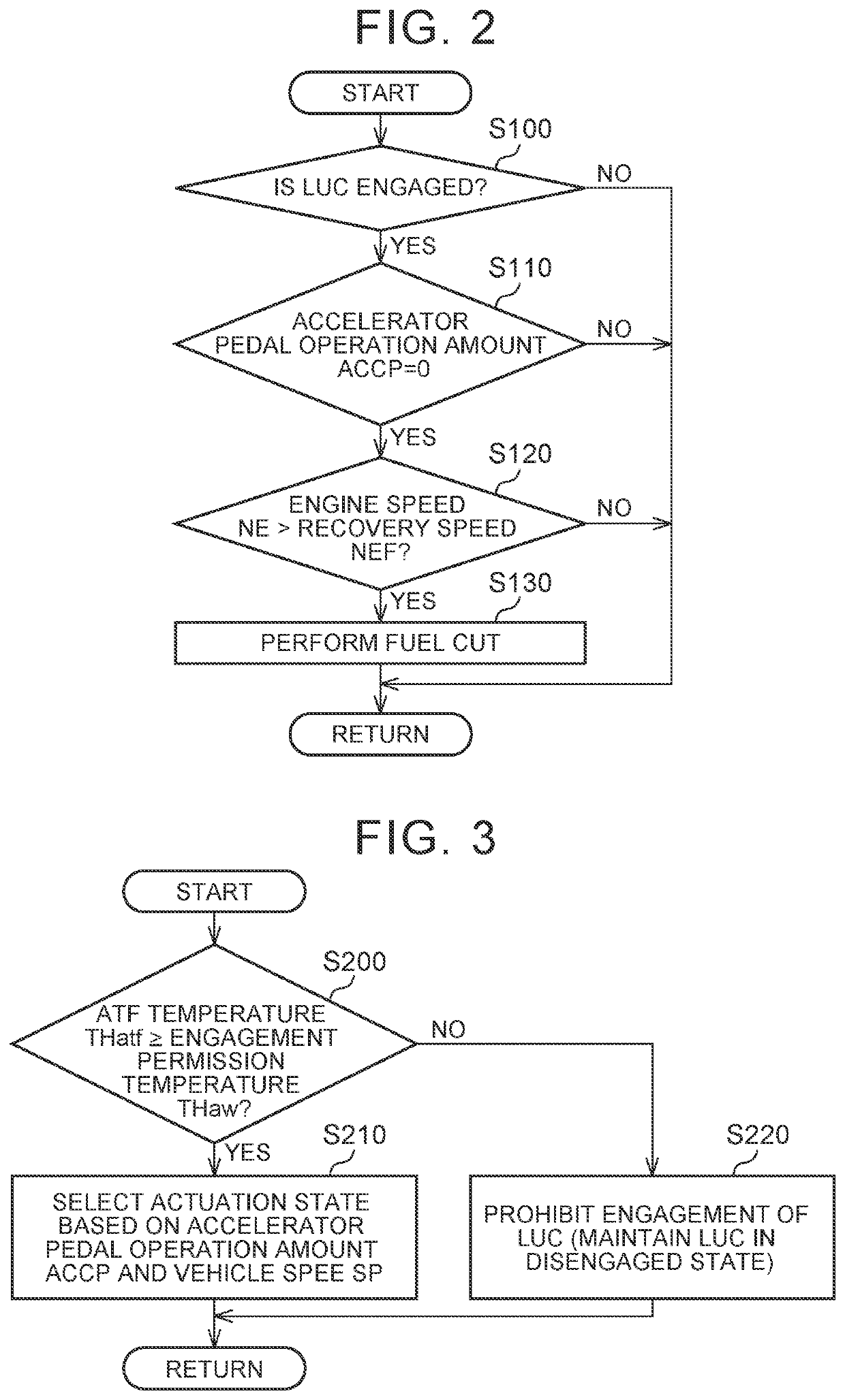
[0004]By the way, in the case where a vehicle having an automatic transmission includes a torque converter having a lock-up clutch, it is preferred to perform the fuel cut for regeneration of the filter when prescribed fuel cut conditions including such a condition that the lock-up clutch is engaged are established. This is because, in the case where the lock-up clutch is engaged, a time required for an engine speed to be reduced from the engine speed at a start of the fuel cut to the engine speed recovered from the fuel cut is extended. Thus, compared to a case where the lock-up clutch is disengaged, a time for performing the fuel cut is extended. In this way, it is possible to secure a time for regenerating the filter.
[0005]However, when a temperature of a fluid that actuates the lock-up clutch is low, viscosity of the fluid is high, and controllability of the lock-up clutch is degraded. Thus, engaging operation of the lock-up clutch is prohibited until the temperature of such a fluid reaches an engagement permission temperature. As a result, when the temperature of the fluid is low, the above-described fuel cut conditions are less likely to be established, and thus the opportunity to regenerate the filter by the fuel cut is reduced.
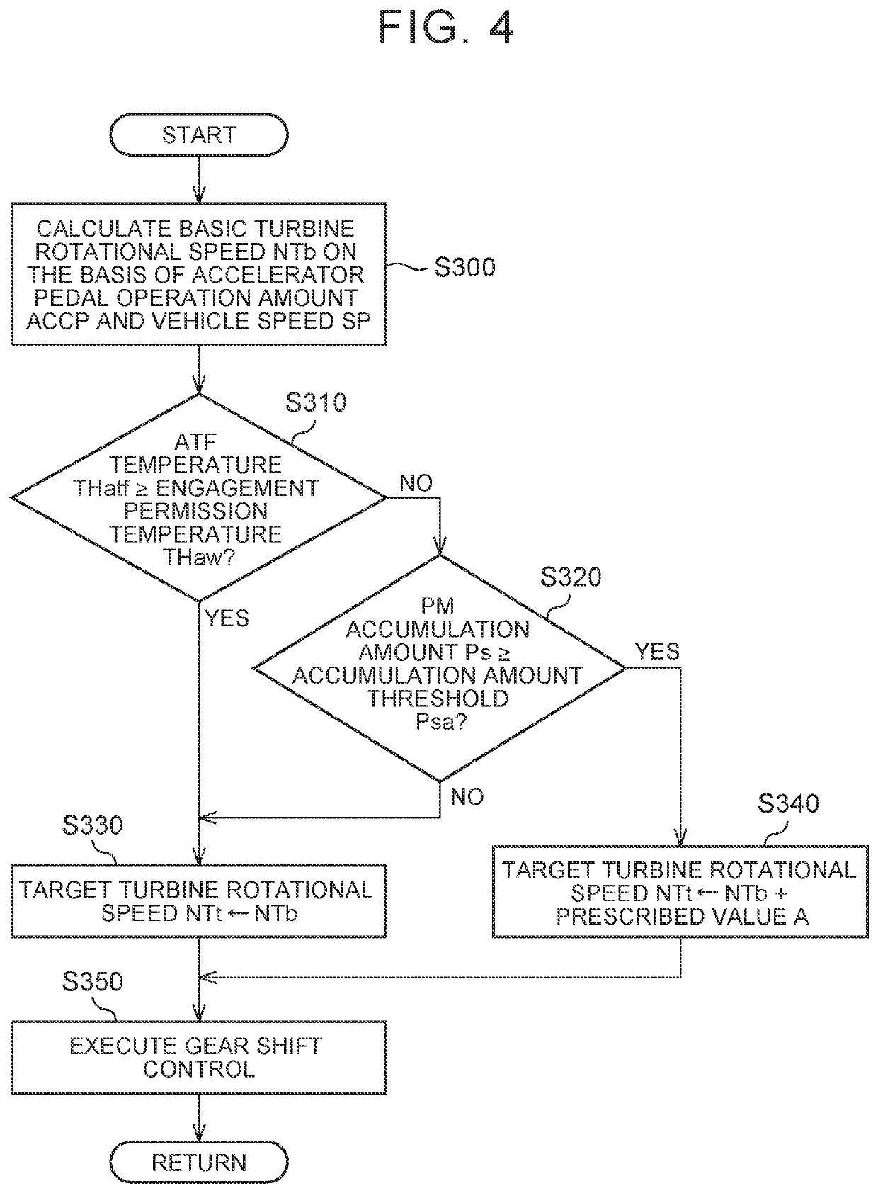
[0008]When the rotational speed of the turbine impeller is increased, just as described, stirring of the fluid in the torque converter is promoted, and a temperature increase in the fluid is thereby promoted. Thus, the temperature of the fluid promptly reaches the engagement permission temperature. Accordingly, even in a state where the temperature of the fluid is low, the lock-up clutch can promptly be brought into an engaged state, and thus the above-described fuel cut condition is likely to be established. Just as described, according to this configuration, the temperature increase of the fluid is promoted. Thus, it is possible to promptly increase an opportunity to regenerate the filter by fuel cut.
[0010]According to this configuration, the gear shift ratio of the continuously variable transmission is controlled such that the rotational speed of the turbine impeller becomes the increased target turbine rotational speed. In this way, the rotational speed of the turbine impeller is increased.

Problems solved by technology

However, when a temperature of a fluid that actuates the lock-up clutch is low, viscosity of the fluid is high, and controllability of the lock-up clutch is degraded.

Method used


Image

  • In-vehicle controller
  • In-vehicle controller
  • In-vehicle controller

Examples


Embodiment Construction

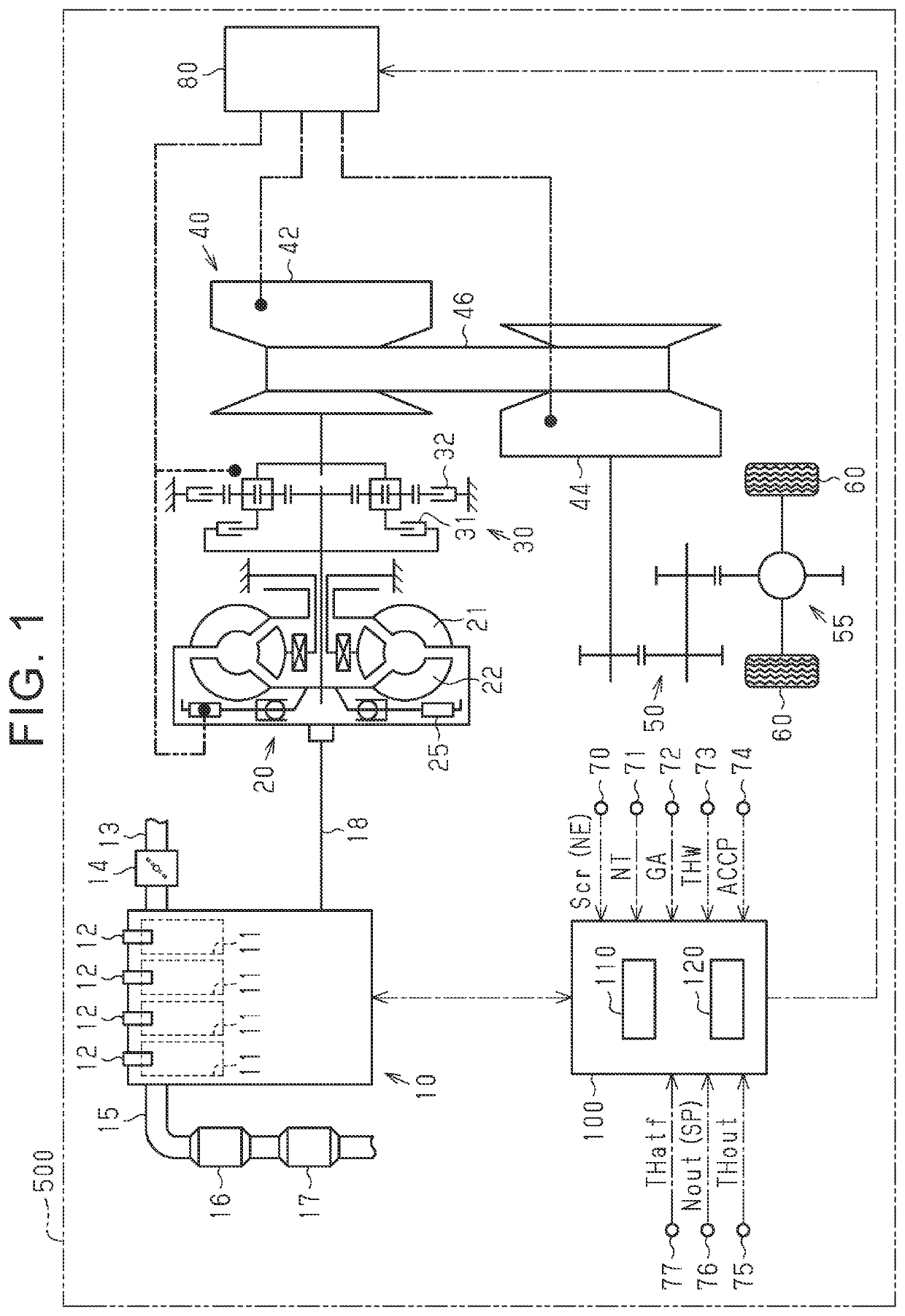
[0018]A description will be made on an embodiment of an in-vehicle controller with reference to FIG. 1 to FIG. 5. As illustrated in FIG. 1, an internal combustion engine 10 including cylinders 11 is mounted on a vehicle 500. An intake passage 13 is connected to an intake port of each of the cylinders 11. The intake passage 13 is provided with a throttle valve 14 for regulating an intake air amount.

[0019]The internal combustion engine 10 includes fuel injection valves 12 for supplying fuel to the cylinders 11. In a combustion chamber of each of the cylinders 11, air-fuel mixture of air suctioned through the intake passage 13 and the fuel injected from the fuel injection valve 12 is ignited by spark discharge and is thereby burned. Exhaust gas generated by burning of the air-fuel mixture in the combustion chambers is exhausted to an exhaust passage 15 connected to exhaust ports of the internal combustion engine 10.

[0020]The exhaust passage 15 is provided with a three-way catalyst (her...


PUM


Abstract

An in-vehicle controller prohibits engagement of a lock-up clutch when a temperature of a fluid that actuates the lock-up clutch is lower than a prescribed temperature. In addition, the in-vehicle controller stops fuel injection by a fuel injection valve when fuel cut conditions including such a condition that the lock-up clutch is engaged are established. Under a situation where the temperature of the fluid is lower than the prescribed temperature, in the case where a PM accumulation amount on a filter is equal to or larger than an accumulation amount threshold, the in-vehicle controller executes speed increase processing so as to execute gear shift control of a continuously variable transmission such that a rotational speed of a turbine impeller in a torque converter is increased to be higher than that in a case where the PM accumulation amount is smaller than the accumulation amount threshold.

Description

INCORPORATION BY REFERENCE[0001]The disclosure of Japanese Patent Application No. 2018-212679 filed on Nov. 13, 2018 including the specification, drawings and abstract is incorporated herein by reference in its entirety.BACKGROUND1. Technical Field[0002]The present disclosure relates to an in-vehicle controller.2. Description of Related Art[0003]For example, in Japanese Patent Application Publication No. 2018-90154 (JP 2018-90154 A), an internal combustion engine that includes, in an exhaust passage, a filter for catching particulate matter (hereinafter referred to as PM) in exhaust gas is disclosed. In this internal combustion engine, so-called fuel cut, in which fuel injection from a fuel injection valve is stopped, is performed to supply oxygen to the filter. In this way, the PM accumulated in the filter is burned to regenerate the filter.SUMMARY[0004]By the way, in the case where a vehicle having an automatic transmission includes a torque converter having a lock-up clutch, it i...

Claims


Application Information

Patent Timeline
Patent Type & Authority Patents(United States)
IPC IPC(8): B60W10/02F02D41/02B60W10/06B60W10/101F01N3/023F16H45/02F16H41/24
CPCF02D41/025B60W10/023B60W10/06B60W10/101F01N3/023F02D41/029B60W2510/107B60W2710/024B60W2710/0627B60W2710/1005F16H41/24F16H45/02B60W10/02B60W50/00B60W2710/02B60W2710/06B60W2710/10F02D41/123F02D41/0215F02D2200/101Y02T10/12F01N2900/0404Y02T10/40
Inventor IWASAKI, RYOTASHINOHARA, YOSHITSUGU
Owner TOYOTA JIDOSHA KK
Learn More