

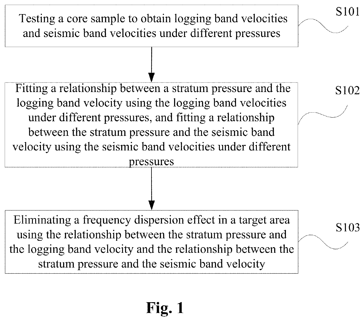
Method, apparatus, and system for eliminating frequency dispersion effect
a frequency dispersion effect and frequency technology, applied in the field of seismic data processing technologies, can solve the problems of insufficient seismic resolution, inability to meet the requirement, and limited methods, so as to improve the quantitative interpretation accuracy of the reservoir inversion result, improve the time-depth matching relationship, and improve the reliability of the spatial position of the reservoir in the time domain.
- Summary
- Abstract
- Description
- Claims
- Application Information
AI Technical Summary
Benefits of technology
Problems solved by technology
Method used
Image

Examples
Embodiment Construction
[0043]In order that those skilled in the art can better understand the technical solutions in the present disclosure, the technical solutions in the embodiments of the present disclosure will be described clearly and completely as follows with reference to the drawings in the embodiments of the present disclosure. Obviously, those described are merely parts, rather than all, of the embodiments of the present disclosure. Based on the embodiments in the present disclosure, any other embodiment obtained by those skilled in the art without paying any creative labor should fall within the protection scope of the present disclosure.
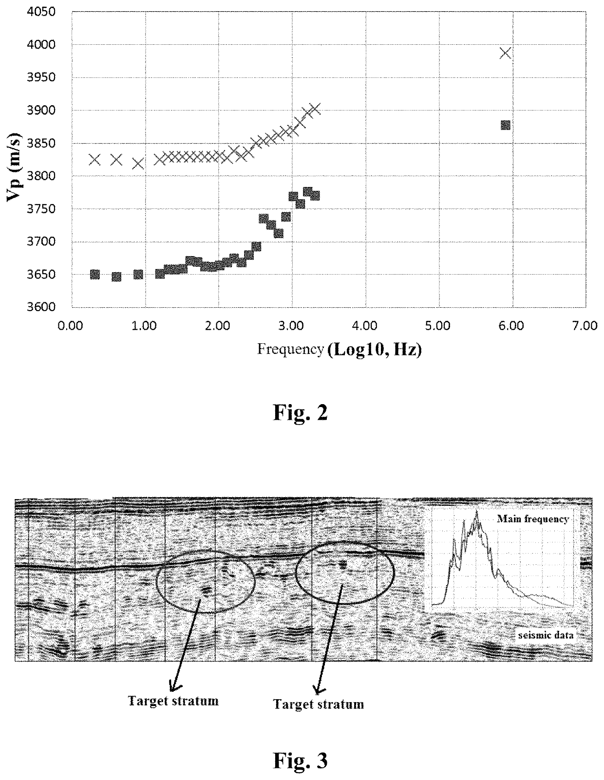
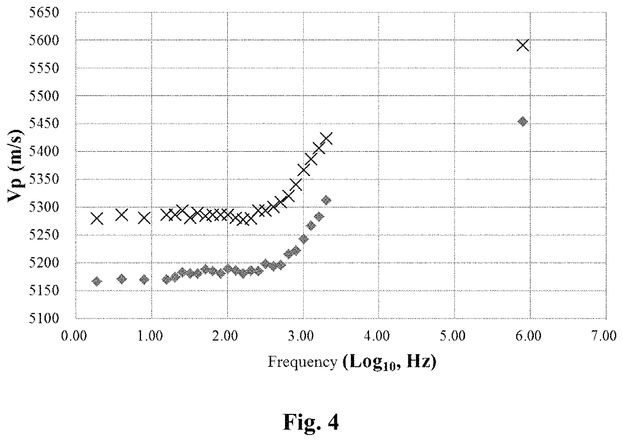
[0044]Those skilled in the art always know the existence of the frequency dispersion phenomenon. The logging velocity acquisition frequency involved in the petroleum exploration is in a level of kHz, while the seismic acquisition excitation focus frequency is in a level of tens to hundreds Hz, and there is an obvious frequency difference therebetween. The frequ...
PUM
 Abstract
Description
Claims
Application Information