Sink unit arrangement, galley compartment and galley

a technology for sink units and compartments, applied in water installations, galleys, constructions, etc., can solve the problem of small installation space requirements of drip tray in the region of the worktop, and achieve the effect of reducing the installation space requirement, reducing the installation space requirements, and reducing the installation spa

Active Publication Date: 2021-03-09
AIRBUS OPERATIONS GMBH
View PDF23 Cites 0 Cited by
  • Summary
  • Abstract
  • Description
  • Claims
  • Application Information

AI Technical Summary

Benefits of technology

[0013]The sink unit arrangement preferably further comprises a particle filter, which serves to prevent the entry of particles into the wastewater system and, in particular, into the drain valve connected to the outflow. In the operation of the sink unit arrangement, proper functioning of the particle filter is particularly important, as particles, such as food residues or the like, for example, which are drained from the drip tray via the outflow, can cause blockages and / or damage to the drain valve. The particle filter is preferably arranged in the outflow in such a way adjacent to the second section of the drip tray that the particle filter is accessible via the second section of the drip tray. The particle filter can then be serviced particularly easily and exchanged if necessary.
[0016]The drainage grille is preferably attached detachably or swivelably to the drip tray, at least in the region of its second section. The drainage grille can then be detached from the second section of the drip tray or swiveled into a position in which it frees the second section of the drip tray. Unobstructed access to the particle filter is facilitated thereby. However, the drainage grille is preferably attached detachably or swivelably to the drip tray also in the region of its first section, in order to make the first section of the drip tray accessible if required, for example for cleaning purposes.
[0017]In its first section the drainage grille can be provided with first grille openings that have a greater cross section than second grille openings provided in the second section of the drainage grille. The formation of the second section of the drainage grille with smaller grille openings prevents liquids that contain excessively large or too many particles from being poured into the second section of the drip tray and being able to cause blockages of the particle filter there. In contrast to this, larger particles, which are introduced into the first section of the drip tray, do not get directly into the outflow. On the contrary, it is possible, by removing the drainage grille, to clean the first section of the drip tray of these particles before they get into the outflow.
[0018]In a preferred embodiment of the sink unit arrangement, the drip tray is designed and arranged in such a way relative to the worktop that an access surface of the drip tray is substantially aligned with an upper side of the worktop forming a work surface. Furthermore, the drainage grille is preferably designed and arranged in such a way relative to the worktop that a drainage surface of the drainage grille is substantially aligned with an upper side of the worktop forming a work surface. When the sink unit arrangement is installed in a galley, sufficient free space is created in a galley region above the drip tray by such a configuration of the sink unit arrangement so that a tap can be installed there at a desired height, for example, without the top compartments of the galley having to be shifted upwards.
[0019]The dimensions, i.e., in particular the width and the length of the second section of the drip tray, are preferably adapted to the dimensions, i.e., in particular, the width and the length of the free space provided to take up at least a portion of the second section of the drip tray adjacent to the installation opening provided in the worktop. The first section of the drip tray can have a width that is greater than a width of the second section of the drip tray. In addition or alternatively to this, the first section of the drip tray can have a length that is greater than a length of the second section of the drip tray. Liquids can thereby be introduced more easily into the first section of the drip tray. Nevertheless, the dimensions of the first section of the drip tray are preferably kept as small as possible in order to minimize the installation space requirement of the drip tray in the region of the worktop.
[0026]The installation space can be arranged adjacent to a side wall or an intermediate wall of the galley compartment. However, the installation space is preferably integrated in a particularly space-saving manner into a side wall or an intermediate wall of the galley compartment. An installation of the installation space in a side wall or adjacent to a side wall of the galley compartment suggests itself, in particular, if the galley compartment has smaller dimensions. An installation of the installation space, in an intermediate wall or adjacent to an intermediate wall of the galley compartment, is advantageous, on the other hand, if the galley compartment is a galley compartment of larger dimensions.

Problems solved by technology

Nevertheless, the installation space requirement of the drip tray in the region of the worktop is small, as a portion of the volume of the drip tray is taken up in the free space adjacent to the installation opening formed in the worktop.

Method used


Image

  • Sink unit arrangement, galley compartment and galley
  • Sink unit arrangement, galley compartment and galley
  • Sink unit arrangement, galley compartment and galley

Examples


Embodiment Construction

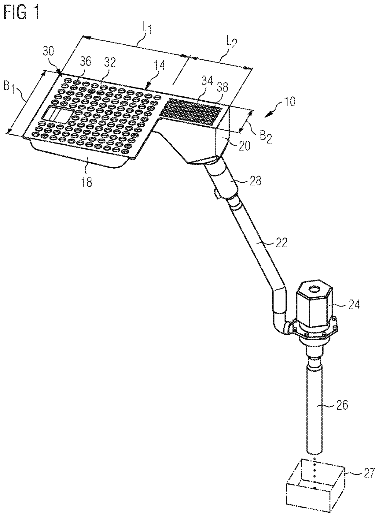
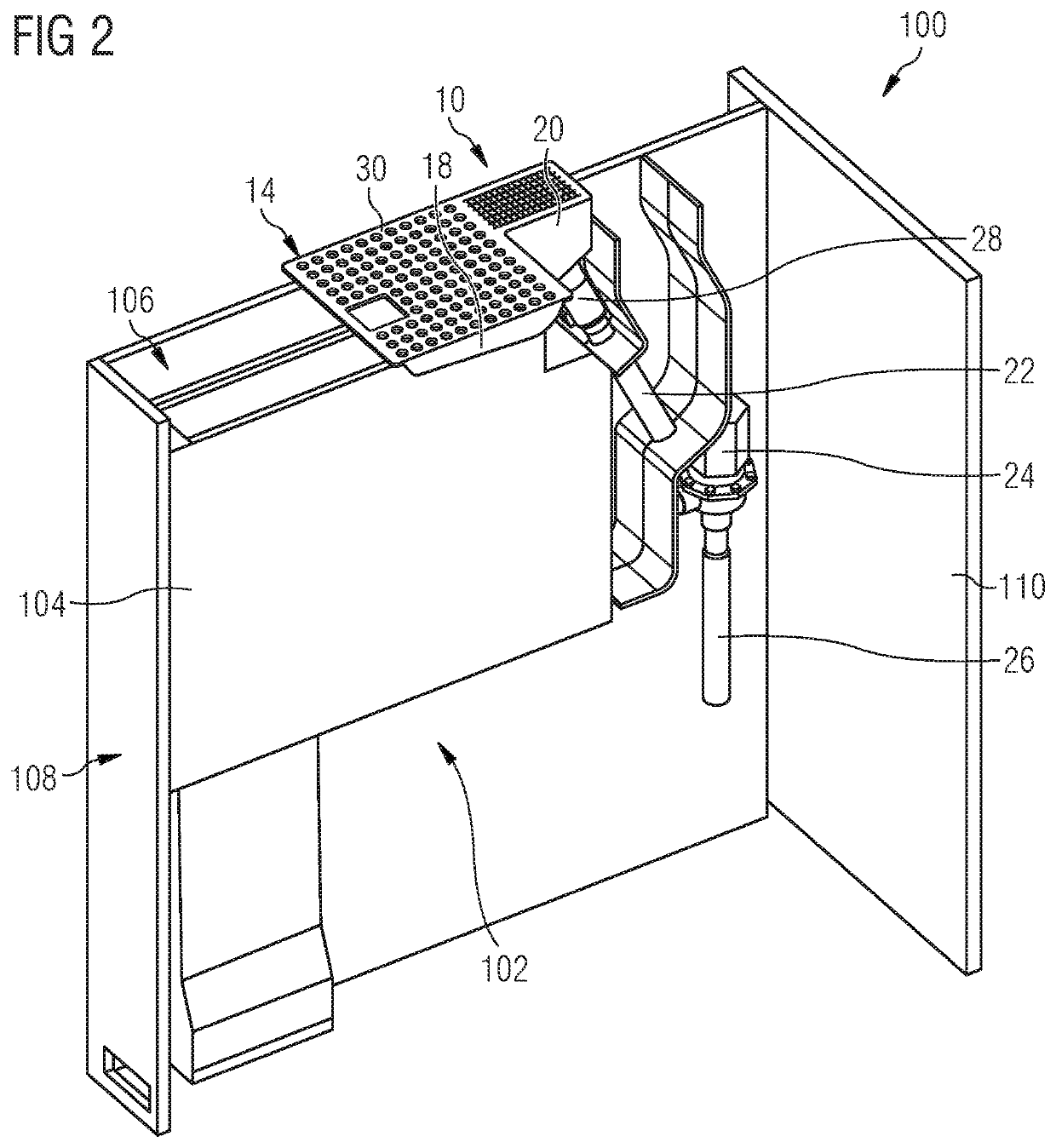
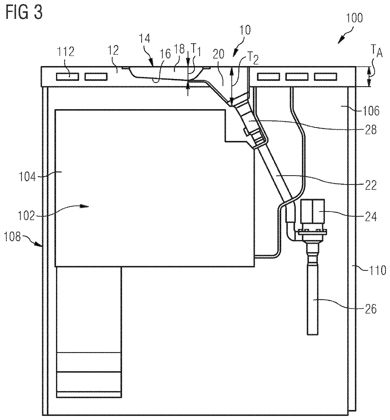
[0035]A sink unit arrangement 10 illustrated in the figures, which is suitable, in particular, for installation in a galley of an airliner, comprises a worktop 12 (see FIGS. 3 and 4). If the sink unit arrangement 10, as shown in FIGS. 2, 3 and 4, is installed in a galley compartment 100 of the aircraft galley, the worktop 12 of the sink unit arrangement 10 forms an upper boundary of the galley compartment 100, so that an upper side of the worktop 12 can be used as a work surface. An interior of the galley compartment 100 is delimited upwards, on the other hand, by an underside of the worktop 12.

[0036]The sink unit arrangement 10 further comprises a drip tray 14, which is arranged in an installation opening 16 provided in the worktop 12. The shape of the installation opening 16 formed in the worktop is adapted to the shape of the drip tray 14 of the sink unit arrangement in such a way that the drip tray 14 is inserted substantially gap-free into the installation opening 16 formed in ...


PUM


Abstract

A sink unit arrangement for a galley provided for installation in a transport vehicle comprises a worktop and a drip tray, which is arranged in an installation opening provided in the worktop and comprises a first section and a second section. The second section has a depth which is greater than a depth of the first section and protrudes through the installation opening provided in the worktop into a free space adjacent to the installation opening.

Description

CROSS-REFERENCES TO RELATED APPLICATIONS[0001]This application claims the benefit of the German patent application No. 10 2017 205 136.1 filed on Mar. 27, 2017, the entire disclosures of which are incorporated herein by way of reference.BACKGROUND OF THE INVENTION[0002]The invention relates to a sink unit arrangement for a galley provided for installation in a transport means, in particular an aircraft. The invention further relates to a galley compartment equipped with such a sink unit arrangement and a galley equipped with such a sink unit arrangement and / or such a galley compartment.[0003]Modern airliners are normally equipped with onboard kitchens, so-called galleys, known, for example, from DE 10 2006 023 047 B4 or U.S. Pat. No. 7,780,114 B2. The galleys are usually installed in the doorway areas of the aircraft cabin and have a carcass with a base structure delimited by a worktop and top compartments arranged above the worktop. Kitchen appliances such as e.g., coffee machines,...

Claims


Application Information

Patent Timeline
Patent Type & Authority Patents(United States)
IPC IPC(8): E03C1/182B64D11/04B64D13/08B64D11/00B64D13/06
CPCE03C1/182B64D11/0007B64D11/04B64D13/08B64D2013/0629
Inventor DAHMS, TOBIASBIELIK, PETERLANGE, ROLAND
Owner AIRBUS OPERATIONS GMBH
Why Eureka
Try Eureka