

Hydropneumatic piston accumulator
- Summary
- Abstract
- Description
- Claims
- Application Information
AI Technical Summary
Benefits of technology
Problems solved by technology
Method used
Image

Examples
Embodiment Construction
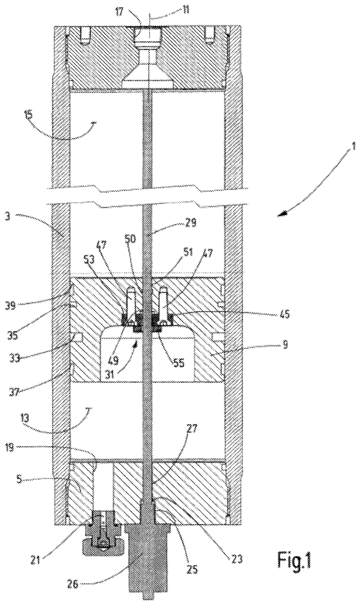
[0033]The invention will now be explained by way of examples depicted in FIGS. 1 to 12 in which the piston accumulator is fitted with a magnetostrictive measuring system. FIG. 13 shows an exemplary embodiment with an ultrasonic measuring system.
[0034]The exemplary embodiments of the piston accumulator according to the invention shown in the drawings comprise an accumulator housing 1, which in all the exemplary embodiments shown has a cylindrical pipe 3 as a main part that forms a round, hollow cylinder. The cylindrical pipe 3 is tightly closed at both ends by screwed-in housing covers 5 and 7, between which a piston 9 is freely moveable along the longitudinal housing axis 11. The piston 9 separates a gas-side working chamber 13, which is filled to a certain filling pressure with a process gas, such as N2, as a compressible medium, from a working chamber 15, which is filled with an incompressible medium, such as hydraulic oil. To connect said working chamber 15 to an associated hydra...
PUM
 Abstract
Description
Claims
Application Information