Pressure accumulation container

a technology of accumulator vessel and cylinder, which is applied in the direction of container discharging methods, vessel construction details, electrochemical generators, etc., can solve the problems of vessel failure, accumulator vessel safety remarkably fail, etc., and achieve the effect of reducing the running cost of hydrogen station and accumulator vessel renewal cost, easy opening and closing of the lid at the end portion of the cylinder portion, and spreading the hydrogen society

Active Publication Date: 2021-03-09
TOKYO DENKI UNIVERSITY +1
View PDF27 Cites 0 Cited by
  • Summary
  • Abstract
  • Description
  • Claims
  • Application Information

AI Technical Summary

Benefits of technology

[0038]According to the invention, the opening and closing of the lid at the end portion of the cylinder portion becomes easy. Consequently, an inspection for internal minute cracks can be carried out on an accumulator vessel at the shipment from a factory or at periodical inspections while in use. The screwing structure at the openable and closeable structure of the lid can ensure the resistance to fatigue properties and the fatigue crack propagation properties. When used for an accumulator vessel for use, for example, at a hydrogen station, the accumulator vessel of the invention can be used repeatedly while verifying periodically that no crack exists in the interior thereof, whereby the safety of the accumulator vessel in relation to the remaining service life can be ensured. Consequently, the running cost of the hydrogen station and the accumulator vessel renewal cost can be reduced, contributing further to the spread of the hydrogen society.

Problems solved by technology

In the event that a crack is generated in an inner surface of the accumulator vessel, hydrogen comes to contact a leading end of the crack to thereby generate hydrogen environmental embrittlement, which accelerates the propagation of the crack, resulting in concerns about a failure of the vessel.
In a general accumulator vessel having an accumulator vessel structure in which a threaded portion where the accumulator vessel is opened and closed is brought into direct contact with hydrogen, hydrogen environmental embrittlement tends to be generated easily at a stress concentrated portion in the threaded portion, and this damages remarkably fail in safety of the accumulator vessel.

Method used


Image

  • Pressure accumulation container
  • Pressure accumulation container
  • Pressure accumulation container

Examples


embodiment 1

[0046]An embodiment of the invention will be described as below.

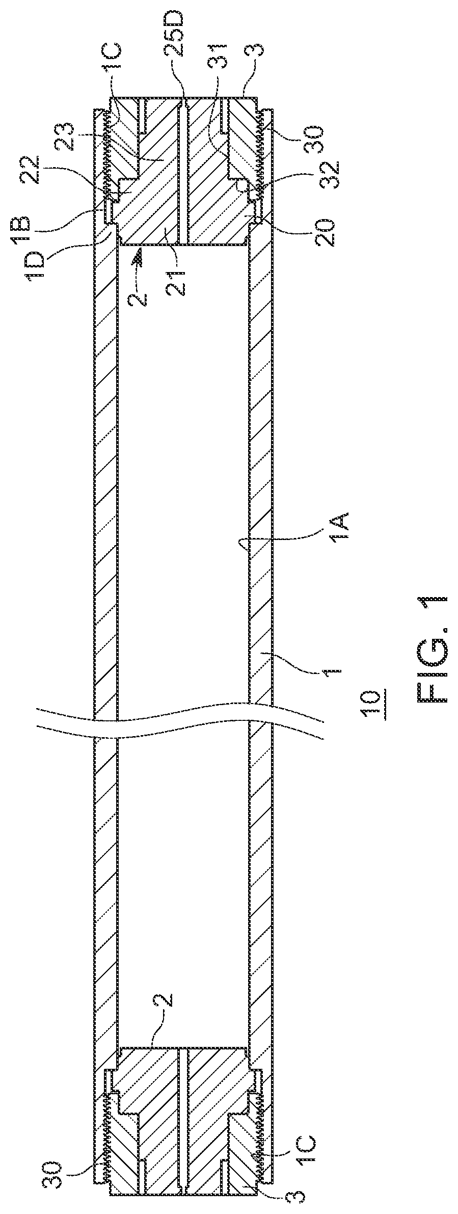
[0047]A hydrogen gas accumulator vessel 10 of this embodiment has a circularly cylindrical cylinder portion 1 made of steel, lid portions 2 configured to close tightly end portions of the circularly cylindrical cylinder portion 1 in such a way as to open them as required, and screwable portions 3 where to fix the lid portions 2 in place in the circularly cylindrical cylinder portion 1. The hydrogen gas accumulator vessel 10 corresponds to an accumulator vessel of the invention. Additionally, in this embodiment, both the end portions of the circularly cylindrical cylinder portion 1 are openable and closeable end portions.

[0048]A Mannesmann-type vessel in which both end openings are tighten or an Ehrhardt-type seamless vessel (a so-called bomb) is used sometimes as a conventional hydrogen gas accumulator vessel. However, in these conventional accumulator vessels, since the opening portions are small, cracks in an inner su...

embodiment 2

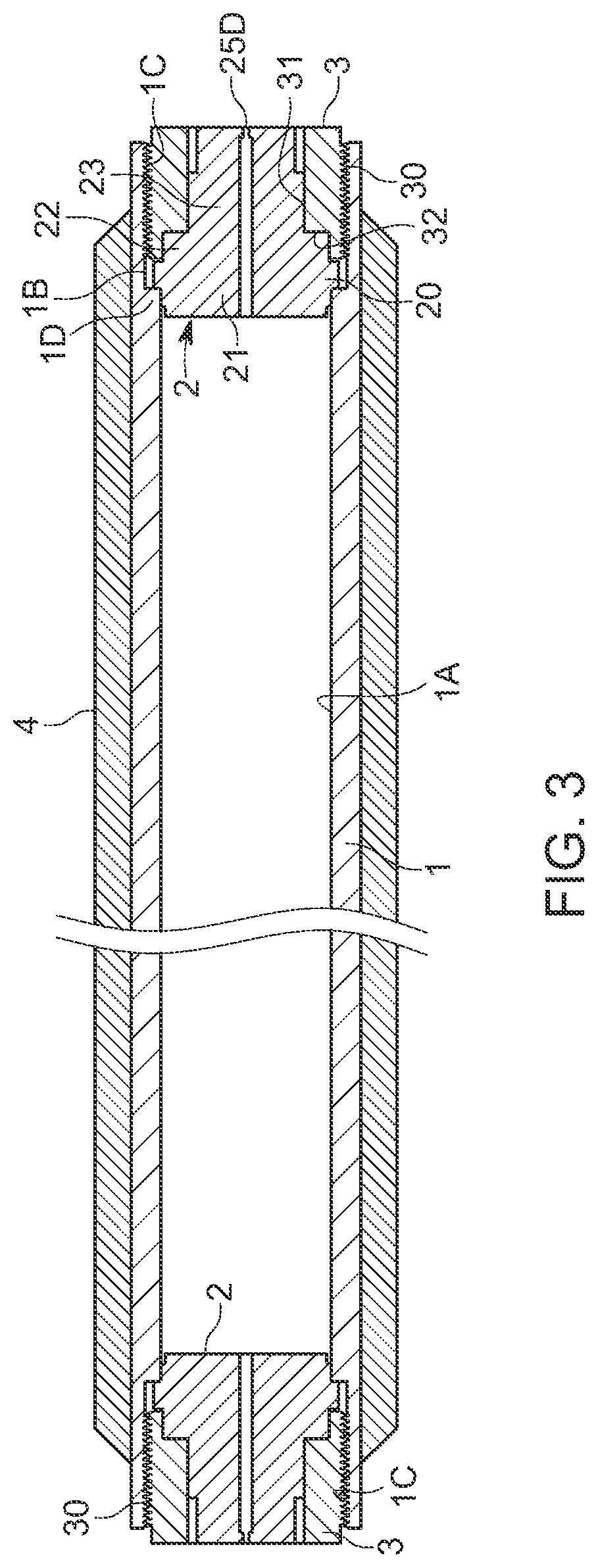
[0075]As shown in FIG. 3, an outer circumferential side of a circularly cylindrical cylinder portion 1 can be hooped with a fiber reinforced plastic 4. The other configurations are remain the same as those of Embodiment 1, and like reference numerals will be given to like portions to those of Embodiment 1, omitting a repeated description thereof.

[0076]As this occurs, there is imposed no specific limitation on the types fiber or plastic material to be used in this invention. For example, carbon fiber can be used as fiber for reinforcement, and epoxy resin or the like can be used as plastic material for covering. It is desirable to use a continuous fiber as fiber for reinforcement. There is imposed no specific limitation on the thickness of fiber to be used, either, and the thickness of fiber to be used can be determined in relation to a strength required. In the invention, the outer circumferential side of the circularly cylindrical cylinder portion 1 may not be hooped with the fiber...

embodiment 3

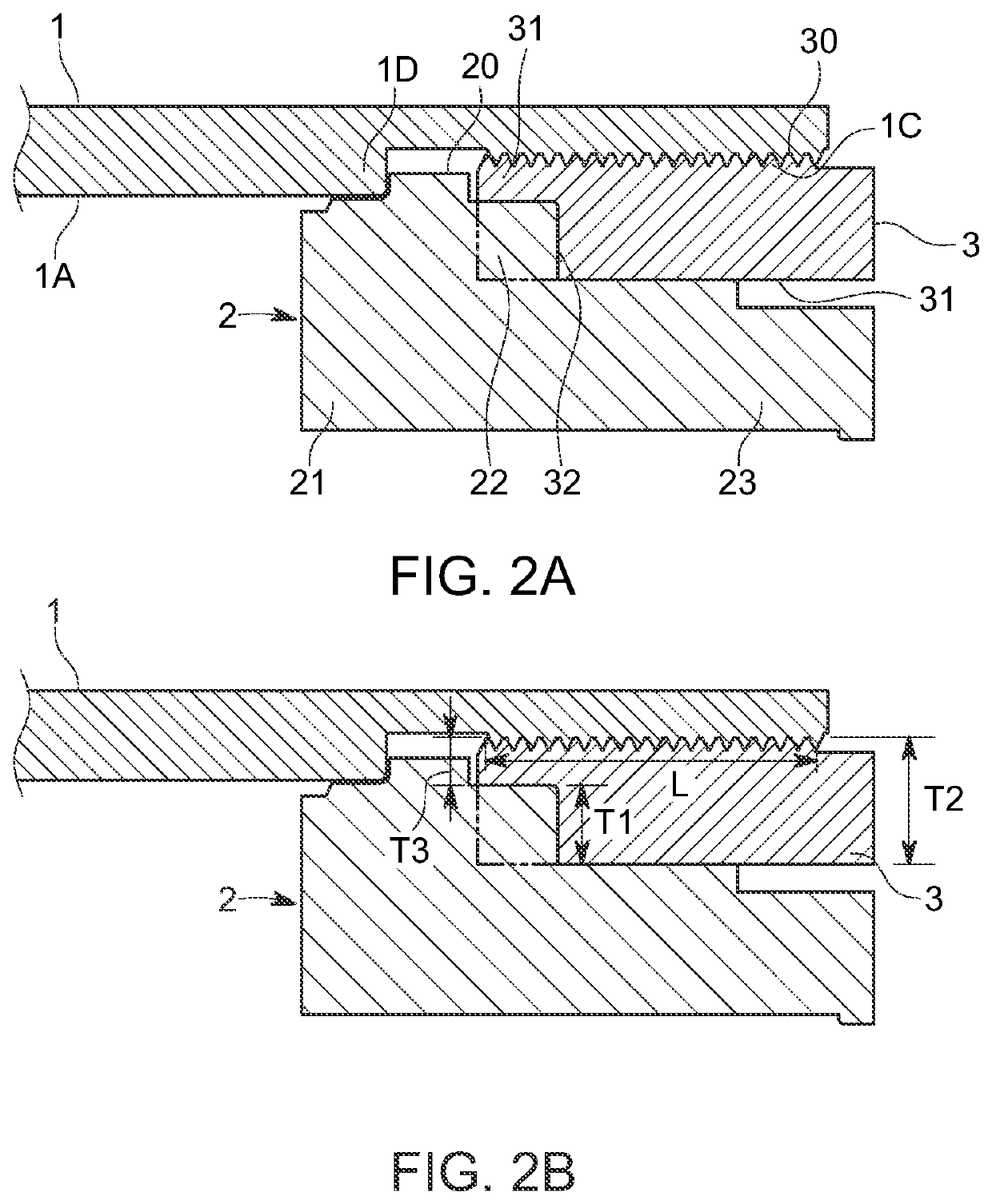
[0079]In Embodiments 1, 2, the ligament portion and the protruding portion 22 are described as being positioned on planes that are radially almost identical, however, the ligament portion and the protruding portion 22 may be disposed so that a clear gap is defined between an outer circumferential surface of the protruding portion 22 and an inner circumferential surface of the ligament portion.

[0080]FIG. 4A shows that a ligament portion of a screwable portion 3A has a thin inner ligament portion 33A and a thick ligament portion 34A. In this embodiment, too, the protruding portion 22 can be brought into contact with a recessed portion of the screwable portion 3A. Although the ligament portion is described as having the two-staged configuration in this embodiment, the number of stages may be increased further. In addition, the ligament portion is described as having the structure in which part of the ligament portion is in contact with or lies near the protruding portion 22, however, t...


PUM

PropertyMeasurementUnit
stress distributionaaaaaaaaaa
surface lengthaaaaaaaaaa
depthaaaaaaaaaa

Abstract

An accumulator vessel (10) includes a screwable portion (3) and a lid portion (2) that is positioned at an axially inner side of the screwable portion and an axially inner surface configures a pressure bearing plane. The lid portion includes a protruding portion (22) extending axially outward on an inner circumferential side, and the protruding portion configured to abut against an axially inner end side of the screwable portion to separate an axially inner surface of the screwable portion on an outer circumferential side thereof apart from an axially outer surface of the lid portion on an outer circumferential side thereof.

Description

TECHNICAL FIELD[0001]The present invention relates to an accumulator vessel that can accumulate high-pressure gas such as pressurized hydrogen gas in an interior thereof and in which a lid at an end portion can be opened and closed.BACKGROUND ART[0002]Conventionally, a high-pressure hydrogen accumulator vessel is used at a hydrogen station, and high-strength low-alloy steel such as Cr—Mo steel is used as a material for such an accumulator vessel. In the event that a crack is generated in an inner surface of the accumulator vessel, hydrogen comes to contact a leading end of the crack to thereby generate hydrogen environmental embrittlement, which accelerates the propagation of the crack, resulting in concerns about a failure of the vessel.[0003]In a general accumulator vessel having an accumulator vessel structure in which a threaded portion where the accumulator vessel is opened and closed is brought into direct contact with hydrogen, hydrogen environmental embrittlement tends to be...

Claims


Application Information

Patent Timeline
Patent Type & Authority Patents(United States)
IPC IPC(8): F17C13/06F16J13/12F16J12/00F17C1/00
CPCF17C13/06F16J12/00F16J13/12F17C1/00F17C2201/0119F17C2201/058F17C2203/0617F17C2203/0619F17C2203/0639F17C2203/0648F17C2203/0665F17C2203/0673F17C2203/0675F17C2205/0305F17C2205/0311F17C2209/234F17C2221/012F17C2223/0123F17C2223/036F17C2260/036F17C2265/066F17C2270/0168F17C2270/0184Y02E60/32F16B5/02F17C1/06F17C2203/012F17C2209/228
Inventor WADA, YORUYANAGISAWA, YUSUKETSUJI, HIROKAZU
Owner TOKYO DENKI UNIVERSITY
Why Eureka
Try Eureka