
Automatically producing an optical blend mask individually adapted to a projector and its position to a projection surface of the projection system

a technology of projection system and automatic production, applied in the direction of projectors, color televisions, instruments, etc., can solve the problems of unfavorable superimposed residual brightness of different projectors, principle inability to project images or partial images, and disturbing residual brightness perception by viewers

Active Publication Date: 2021-03-09
DOMEPROJECTION COM GMBH
View PDF43 Cites 6 Cited by
  • Summary
  • Abstract
  • Description
  • Claims
  • Application Information

AI Technical Summary

Benefits of technology

The patented method produces optical blend masks that significantly reduce or eliminate disadvantages and do not require manual setup. The method involves calculating blending for each individual projection based on a measurement of the overall projection, and distortions of all projector-lens pairs are measured in a so-called blend mask plane. The produced optical blend masks contain registration marks which correspond exactly to the markers of the frames, and can thus be fixed in the frame very precisely. The method also includes optional iterative optimization of the optical blend mask to reduce deviations between the ideal image of blending and the expected blending. The technical effects of the patented method are improved image quality and reduced distortion in large-area projection.

Problems solved by technology

Most projectors are in principle unable to project images or partial images that are displayed in an image part having no brightness, i.e. which are completely black.
When such image areas overlap in the blend zone, the residual brightness of the different projectors is unfavorably superimposed.
In particular, when representing very dark image areas in the overlaps of the partial images, the resulting residual brightness is perceived by a viewer as very disturbing, since the blending has no effect on the residual light.
Since the real projection system is always different from the design or from an ideally planned projection, the results produced with these optical blend masks are not always satisfactory.
The reason for the limited functionality of such optical blend masks is, on the one hand, based on the fact that it is very difficult in practice to construct a projection system exactly according to a given design.
On the other hand, a so-called individual distortion of a projector caused by inaccuracies in the manufacture of the lenses or lens pairs of a projector cannot be taken into account at all or only with a substantial design effort.
The prior art thus has the disadvantages that no optimal compensation for the problem associated with residual brightness occurring in the blend zones of a large-area projection is provided.
In particular, compensation by using an optical blend mask cannot be adapted automatically to the real projection system, which always differs at least partially from a planned design, and / or to existing distortions of the projectors, which likewise always occur in practice.

Method used


Image

  • Automatically producing an optical blend mask individually adapted to a projector and its position to a projection surface of the projection system
  • Automatically producing an optical blend mask individually adapted to a projector and its position to a projection surface of the projection system
  • Automatically producing an optical blend mask individually adapted to a projector and its position to a projection surface of the projection system

Examples


Embodiment Construction

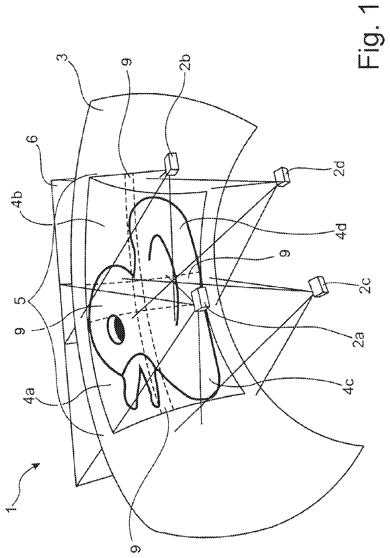
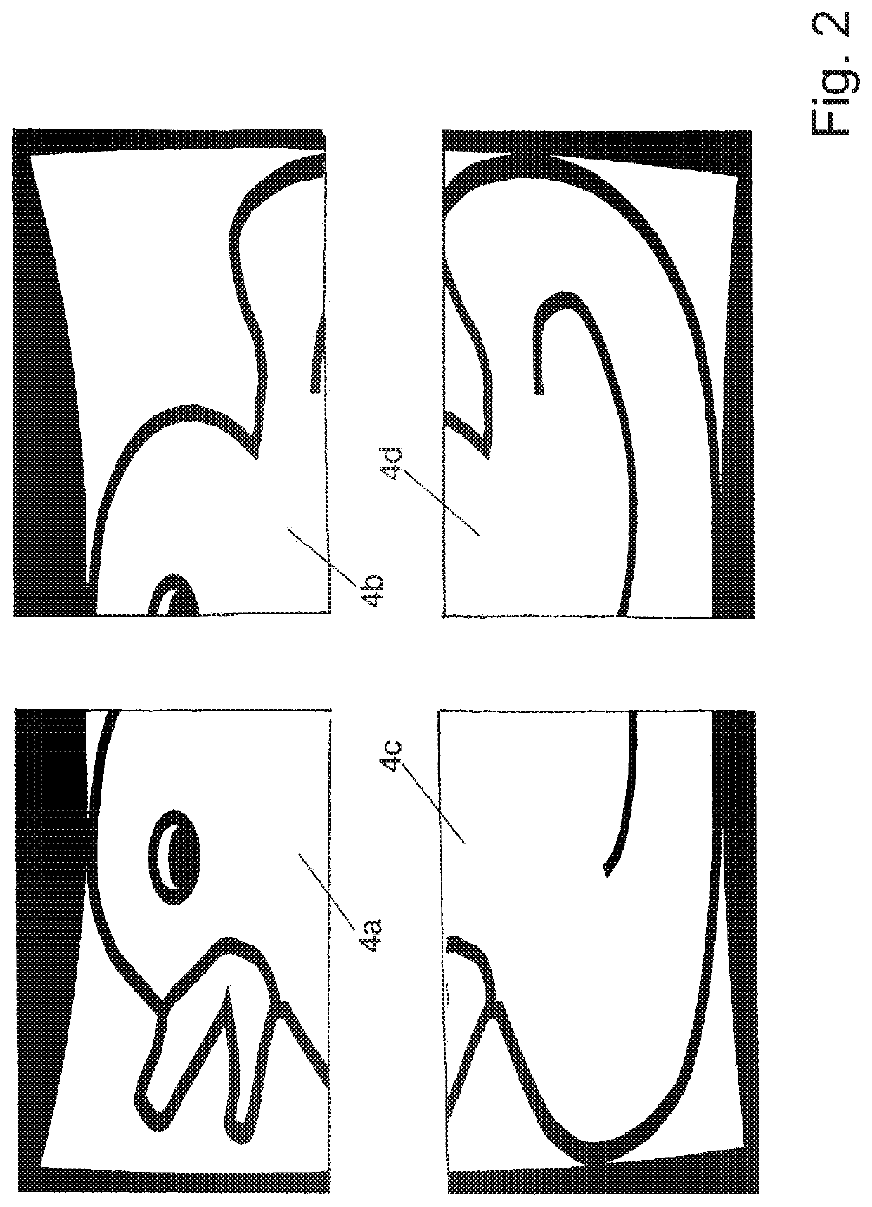
[0066]FIG. 1 shows a projection system 1, which by way of example includes four projectors 2a, 2b, 2c, 2d. Each projector 2a, 2b, 2c, 2d produces a partial image 4a, 4b, 4c, 4d on the projection surface 3, which together produce a large-area projection 5. The generation of this large-area projection 5 takes place in such a way that a blend zone 9 is formed between two adjacent partial images 4a, 4b, 4c, 4d, in which image portions of the adjacent partial images 4a, 4b, 4c, 4d are superimposed. The image signals or video signals of the partial images 4a, 4b, 4c, 4d required for the control of the projectors 2a, 2b, 2c, 2d are generated in a suitable central signal generating unit, which will not be described in detail, since it does not affect the disclosure of the present invention.

[0067]The required partial images 4a, 4b, 4c, 4d are initially generated in the signal generation unit in such a way that the large-area projection 5 can be projected without errors when displayed only on...


PUM


Abstract

A method for automatically producing an optical blend mask arranged in a beam path (8) of a projector (2) in a projection system with two projectors (2), by determining an actual state of the projection system by calibrating and producing an ideal blending, ascertaining an individual distortion of the projector (2) by using a front or back projection surface (11), introduced into the beam path (8), using patterns (13) from which points are derived, ascertaining the alignment and the position of the front or back projection surface (11) within a blend mask plane, calculating the optical blending for a partial image, for positioning and / or a transformation of the ideal blending, adapting the ideal blending for compensating a soft focus, applying the ascertained, individual distortion of the projector (2) to the blending, ascertaining data of the optical blend mask and outputting data for producing the optical blend mask.

Description

[0001]This is an application filed under 35 USC § 371 of PCT / DE2017 / 000389, filed on Nov. 17, 2017, claiming priority to DE 10 2016 013 994.3 filed on Nov. 23, 2016, each of which is herein incorporated by reference in its entirety.BACKGROUND OF THE INVENTION(1) Field of the Invention[0002]The invention relates to a method for automatically producing an optical blend mask which is used in the beam path of a projector in a projection system comprising at least two projectors.(2) Description of Related Art[0003]Large-area projections, which are produced by so-called projection systems, are usually composed of several small projections or partial images, with the individual projection channels which produce the partial images being geometrically distorted and blended in a manner adapted to the projection surface. In this way, a correspondingly large-scale homogeneous projection or display on the projection surface can be produced, for example, by using four projectors, which each produ...

Claims


Application Information

Patent Timeline
IPC IPC(8): H04N9/31G03B21/13G03B21/26
CPCH04N9/3147G03B21/13G03B21/26G03B21/147G03B37/04H04N9/3182H04N9/3185H04N9/3194G02B27/0025G02B5/22
Inventor BEIER, DANIELGULAMHUSSENE, DANILOBODE, CHRISTOPHGULAMHUSSENE, GINOSTEINMANN, CHRISTIAN
Owner DOMEPROJECTION COM GMBH
Learn More