Paddle, plating apparatus equipped with the paddle, and plating method

a technology of plating apparatus and paddle, which is applied in the direction of electrolysis components, transportation and packaging, mixing, etc., can solve the problems of increasing the load on the driving device, and achieve the effect of increasing the agitating power of the paddle and increasing the supply of metal ions

Active Publication Date: 2021-03-16
EBARA CORP
View PDF9 Cites 0 Cited by
  • Summary
  • Abstract
  • Description
  • Claims
  • Application Information

AI Technical Summary

Benefits of technology

[0008]According to an embodiment, there is provided a paddle which, without an increase in the reciprocating speed, can generate an increased plating-solution agitating power. According to embodiments, there are provided a plating apparatus equipped with the paddle, and a plating method using the paddle.
[0020]According to the above-described embodiments, the plating-solution agitating power of the paddle can be increased without increasing the reciprocating speed of the paddle. Therefore, the use of the paddle in plating of a substrate can increase the supply of metal ions in a plating solution to the substrate.

Problems solved by technology

However, increasing the reciprocating speed of the paddle 205 for increasing the plating-solution agitating power can cause scattering of the plating solution in the plating tank 201, or may increase a load on a driving device that drives the paddle 205.

Method used


Image

  • Paddle, plating apparatus equipped with the paddle, and plating method
  • Paddle, plating apparatus equipped with the paddle, and plating method
  • Paddle, plating apparatus equipped with the paddle, and plating method

Examples


Embodiment Construction

[0054]Embodiments will now be described with reference to the drawings. In the drawings described herein below, the same reference numerals are used to refer to the same or equivalent components or elements, and duplicate descriptions thereof are omitted.

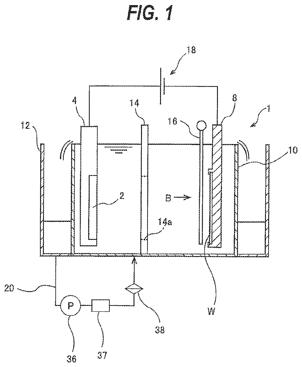
[0055]FIG. 1 is a schematic view of a plating apparatus according to an embodiment. As shown in FIG. 1, the plating apparatus includes a plating tank 1 for holding a plating solution therein, an anode 2 disposed in the plating tank 1, an anode holder 4 holding the anode 2, and a substrate holder 8. The substrate holder 8 is configured to detachably hold a substrate W, such as a wafer, and immerse the substrate W in the plating solution held in the plating tank 1. The plating apparatus of this embodiment is an electroplating apparatus which plates a surface of the substrate W with a metal by passing an eclectic current through the plating solution.

[0056]The substrate W may be, for example, a semiconductor substrate, a glass substrate...


PUM

PropertyMeasurementUnit
distanceaaaaaaaaaa
distanceaaaaaaaaaa
widthaaaaaaaaaa

Abstract

A paddle for agitating a plating solution by reciprocating parallel to a surface of a substrate is disclosed. The paddle includes a plurality of vertically-extending agitation rods. Each agitation rod includes: a planar portion perpendicular to a reciprocating direction of the paddle; two slope surfaces extending from side ends of the planar portion in directions closer to each other, the two slope surfaces being symmetric with respect to a center line of the agitation rod, the center line being perpendicular to the planar portion; and a tip portion connected with the two slope surfaces.

Description

CROSS REFERENCE TO RELATED APPLICATION[0001]This document claims priority to Japanese Patent Application No. 2017-019507 filed Feb. 6, 2017, the entire contents of which are hereby incorporated by reference.BACKGROUND[0002]FIG. 32 is a schematic view of a plating apparatus. As shown in FIG. 32, the plating apparatus includes a plating tank 201 for holding a plating solution therein, an anode 202 disposed in the plating tank 201, an anode holder 203 holding the anode 202, and a substrate holder 204. The substrate holder 204 is configured to detachably hold a substrate W, such as a wafer, and immerse the substrate W in the plating solution held in the plating tank 201. The anode 202 and the substrate W are each disposed in a vertical position and are disposed opposite each other in the plating solution.[0003]The plating apparatus further includes a paddle 205 for agitating the plating solution in the plating tank 201, and a regulation plate 206 for regulating the distribution of elect...

Claims


Application Information

Patent Timeline
Patent Type & Authority Patents(United States)
IPC IPC(8): B01F11/00C25D17/00C25D21/10C25D17/06C25D17/02C25D21/18C25D21/12
CPCB01F11/0082B01F11/0097C25D17/001C25D17/02C25D17/06C25D21/10C25D21/18B01F2215/0096C25D21/12C25D5/08B01F31/441B01F31/70C25D17/14C25D5/06B01F2101/58
Inventor MASUDA, YASUYUKISHIMOYAMA, MASASHIFUJIKATA, JUMPEIWAKUDA, YOHEICHANG, SHAO HUA
Owner EBARA CORP
Why Eureka
Try Eureka