Light system with a single one-part lens

a one-part lens and light system technology, applied in the field of light systems, can solve the problems of less robustness, negatively changing the imaging properties, and the system is more complex, and therefore more expensive to manufacture and handle, and achieve the effect of fast and inexpensive production

Active Publication Date: 2021-03-16
MOTHERSON INNOVATIONS CO LTD
View PDF10 Cites 0 Cited by
  • Summary
  • Abstract
  • Description
  • Claims
  • Application Information

AI Technical Summary

Benefits of technology

[0014]The light system thus includes exactly two optical components between the light source and the imaging element, specifically the light source and the imaging lens, in order to be able to image the mask onto a substrate. This arrangement represents a maximally compact system and therefore requires much less installation space than conventional systems consisting of four or more optical elements between light source and imaging element. Due to the one-part form, the optical components can no longer slip against each other and are therefore very robust against impacts and other treatments. As a result, the light system has a consistent image quality throughout its lifetime.
[0043]In a further example of the method, this further includes closing the slit with suitable material, preferably the material of the first or second lens section. By the closing the mask remains stationary in the imaging lens and cannot slip by handling, as for example on a transport or in use. This completely eliminates the possibility of dirt or moisture penetrating through the slit between the mask and the remaining components.

Problems solved by technology

In addition, an increased number of components requires careful adjustment of the components to each other, which makes such a system less robust against impacts, etc., and thus can negatively change the imaging properties over time.
The increased number of components makes the system more complex and therefore more expensive to manufacture and handle.

Method used


Image

  • Light system with a single one-part lens
  • Light system with a single one-part lens
  • Light system with a single one-part lens

Examples


Embodiment Construction

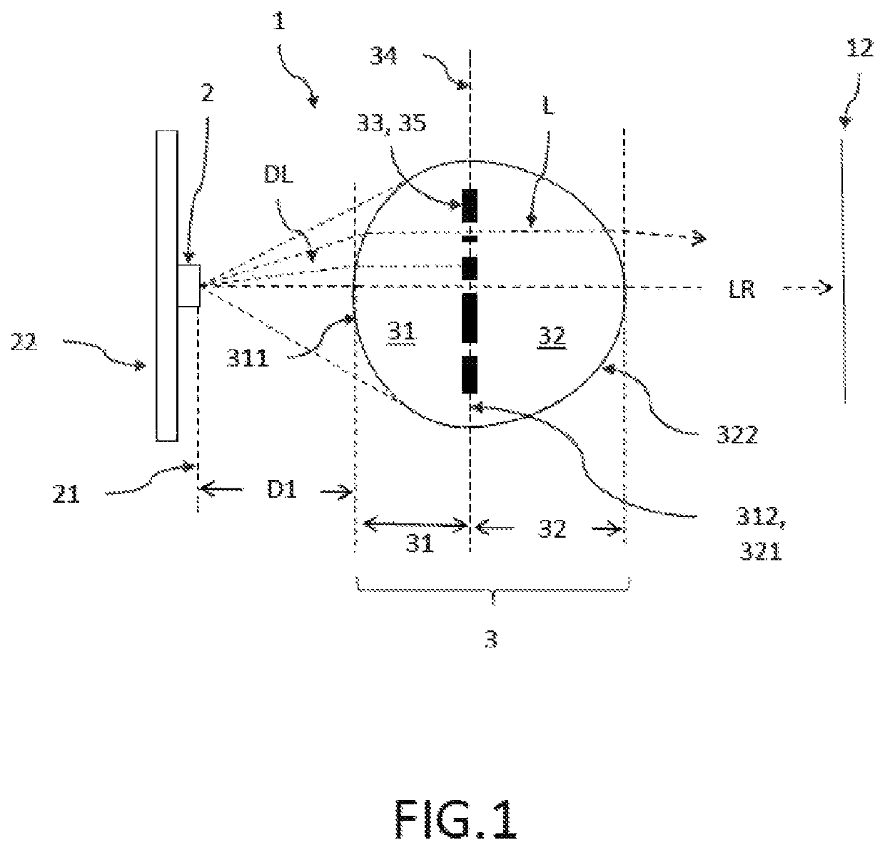
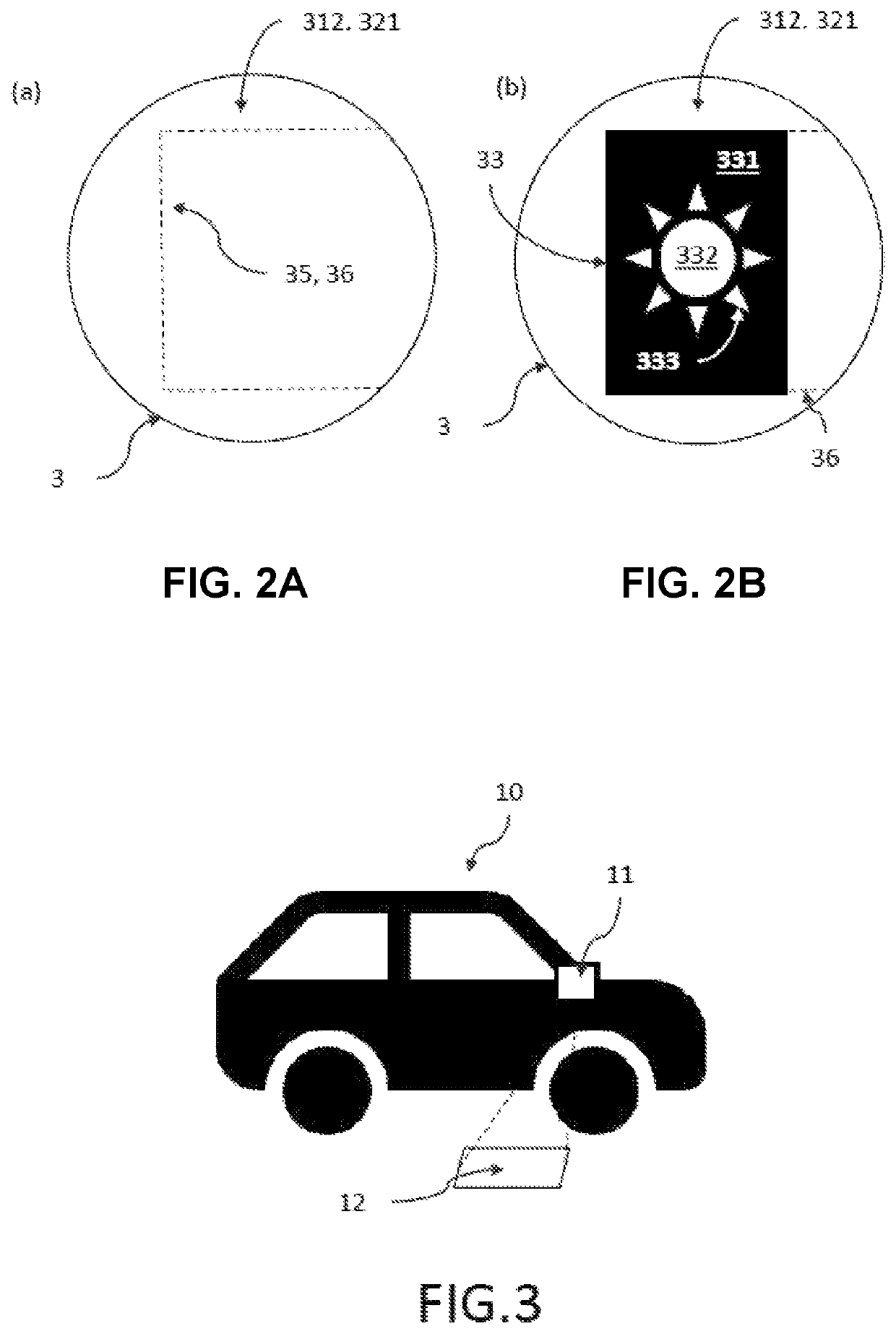
[0051]FIG. 1 is a schematic representation of a lateral view of an example of the light system. The light system 1 includes a light source 2 for emitting divergent light DL and only one imaging lens 3 arranged in front of it in the divergent light DL for imaging the divergent light DL directly received from the light source 2. No further optical components are arranged between the light source 2 and the imaging lens 3 in the light beam. Seen in light propagation direction LR, no further optical components are arranged here up to the projection surface 12, on which the pattern of a mask 33 is projected. Any transparent covers in the light path behind the imaging lens 3 to protect the light system 2 are not regarded as optical components because they do not significantly change the shape, intensity or color of the light.

[0052]The light source 2 has a light exiting surface 21 which is significantly smaller than a maximum surface 34 of the imaging lens 3 perpendicular to the light propa...


PUM


Abstract

A light system includes a light source for emitting divergent light, and only one imaging lens arranged in front of the light source in the divergent light for imaging the divergent light directly received from the light source, where the imaging lens is one-piece fabricated part and comprises a first lens section with a non-structured and convex light entry surface curved in a direction of the light source for the entry of the divergent light of the light source into the imaging lens, a second lens section with a convex light exiting surface curved in a light propagation direction for imaging the light entered, and a mask arranged between the first and second lens sections for modifying the light entered into the first lens section before leaving the light exiting surface.

Description

CROSS-REFERENCE TO RELATED APPLICATION[0001]This application claims the benefit of foreign priority to German Patent Application No. DE 10 2018 113 370.7, filed Jun. 5, 2019, which is hereby incorporated by reference in its entirety for all purposes.BACKGROUND1. Field of the Invention[0002]The present disclosure is generally related to a light system which includes two optical components (light source and imaging lens), a motor vehicle equipped with such a light system and a method for manufacturing this light system.2. Related Art[0003]There are currently several built-in light systems in vehicles. In addition to a light source, these usually have three or more optical components with different optical functions, for example as a collecting lens, as an element for structuring the light and as a dispersing lens for light systems for imaging patterns on backgrounds. Such multi-component systems require a relatively large installation depth and thus stand in the way of the most compac...

Claims


Application Information

Patent Timeline
Patent Type & Authority Patents(United States)
IPC IPC(8): G03B21/20F21V13/10F21V5/04B60Q1/26G03B21/14
CPCF21V13/10B60Q1/2665F21V5/04G03B21/142G03B21/208B60Q2400/50F21S43/50F21S43/26F21S43/14F21V11/08
Inventor RÖTZER, ILKA
Owner MOTHERSON INNOVATIONS CO LTD
Why Eureka
Try Eureka