Imaging system

An imaging system and image-side technology, applied in the field of imaging systems, can solve the problems of poor foreground effect, low pixels, uneven image quality, etc., and achieve the effect of reducing burden ratio, large imaging frame, and improving imaging image quality.

Pending Publication Date: 2019-01-15
舜宇光学(中山)有限公司
View PDF0 Cites 0 Cited by
  • Summary
  • Abstract
  • Description
  • Claims
  • Application Information

AI Technical Summary

Problems solved by technology

[0004] The purpose of the present invention is to provide an imaging system to solve the problems of uneven image quality and low pixels, poor image quality, and poor foreground effect in general visual imaging systems

Method used


Image

  • Imaging system
  • Imaging system
  • Imaging system

Examples


Embodiment approach

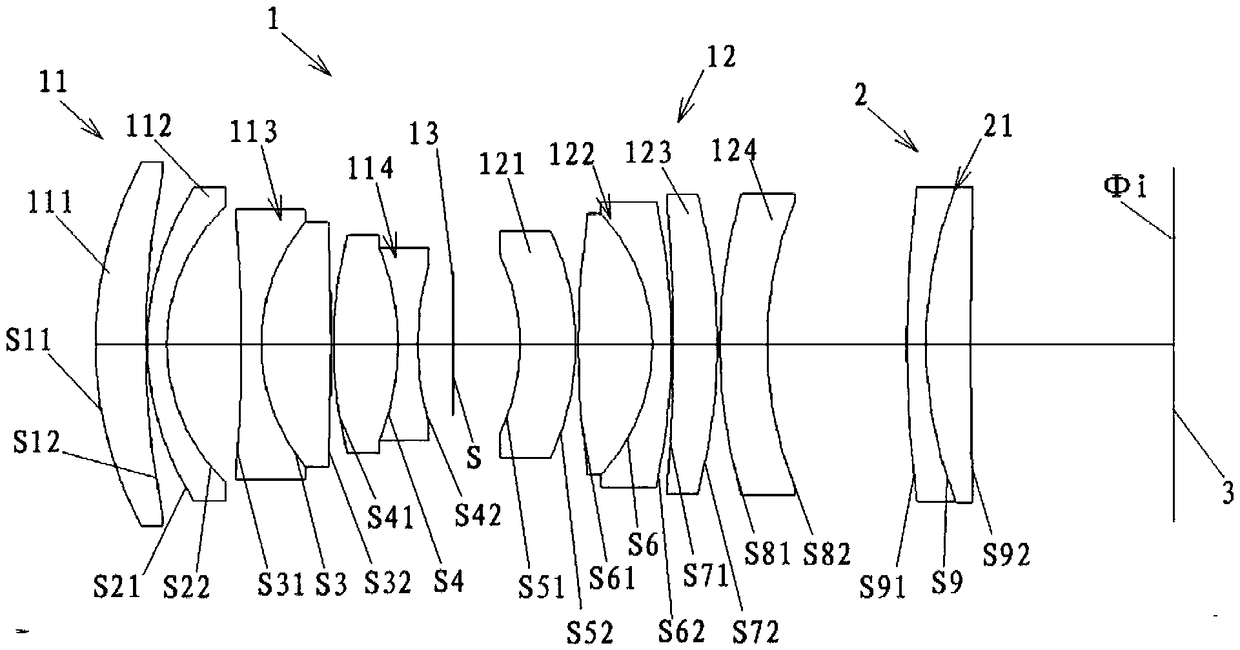
[0144] Such as figure 1 As shown, according to an embodiment of the present invention, the front side lens group 1 includes a first lens group 11 and a second lens group 12. In this embodiment, from the object side to the image side, the first lens group 11 and the second lens group 12 are sequentially arranged along the optical axis. In this embodiment, when imaging from an object at infinity to a short-distance object, the first lens group 11 and the second lens group 12 as a whole move to the object side along the optical axis. In this embodiment, the front lens group 1 further includes a diaphragm 13 . The diaphragm 13 is located between the first lens group 11 and the second lens group 12. When the front lens group 1 is in focus, the first lens group 11 , the second lens group 12 and the diaphragm 13 move together. There are two lens groups in the front lens group 1, which not only realizes focusing in the front lens group, but also makes it easier to reduce the volume...

Embodiment 1

[0226] based on figure 1 The configuration of the imaging system shown is illustrative of this embodiment. see figure 1 As shown, in this embodiment, the third lens 113, the fourth lens 114, the sixth lens 122 and the ninth lens 21 are all cemented lenses, and the rest of the lenses are single lenses (that is, non-cemented lenses). Such as figure 1 As shown, for the convenience of describing the embodiments of the present invention, the mirror surfaces of the lenses of the imaging system of the present invention are numbered from the object side to the image side. therefore. S11 is the object side of the first lens 111 near the object side, S12 is the image side of the first lens 111 near the image side; S21 is the object side of the second lens 112 near the object side, and S22 is the image of the second lens 112 near the image side S31 is the object side of the third lens 113 close to the object side, S32 is the image side of the third lens 113 close to the image side, S...

Embodiment 2

[0236] based on Figure 13 The configuration of the imaging system shown is illustrative of this embodiment. see Figure 13 As shown, in this embodiment, the third lens 113, the fourth lens 114, the sixth lens 122 and the ninth lens 21 are all cemented lenses, and the rest of the lenses are single lenses (that is, non-cemented lenses). Such as Figure 13 As shown, in order to facilitate the description of the embodiment of the present invention, the mirror surfaces of the lenses of the imaging system of the present invention are numbered from the object side to the image side.

[0237] As the data given in Embodiment 2 in Table 1, the parameters of the imaging system of the present invention are as follows:

[0238] ttl=130-174mm; WD>100mm; fg1=83.4; fg2=1030; fgd1=1055; fgd2=64.3; f=80; TF=44.

[0239] The system parameters are: the imaging system is a full-frame Φ46mm photosensitive device, and the aperture value is 3.

[0240] Following table 3 lists the relevant param...


PUM


Abstract

The invention relates to an imaging system. The imaging system comprises a front lens group and a back lens group; from an object side to an image side, the front lens group and the back lens group are orderly arranged along an optical axis; the front lens group has positive focal power, and the back lens group has positive focal power; the back lens group is the fixed lens group with a fixed location, and the front lens group is a focusing lens group and capable of moving along the optical axis; the focal length f of the imaging system and the focal length fg1 of the front lens group satisfies a condition that the fg1/f is more than 1 and less than 1.1; an objective image magnification is between 0 time and a large magnification, and the large magnification is greater than 0.4 times; theimaging object distance is to infinity object from short-distance object, and the short-distance range is within 0.1m. The lens imaging frame is large and the distortion is low, the resolution can achieve 90 million pixels, the imaging is better, more plentiful and delicate, the shallow depth of field effect is more excellent, and the environment change resistance is strong.

Description

technical field [0001] The invention relates to the field of optical imaging, in particular to an imaging system. Background technique [0002] Machine vision refers to the use of machines instead of human eyes for measurement and judgment. The visual lens captures the picture, and converts the captured target into an image signal through an image capture device such as an industrial camera, and then through an image processing system, calculates these signals and extracts target features, such as position, size, appearance, etc., and then according to the preset Conditional output results to realize automatic identification, judgment, measurement and other functions. [0003] With the development of the visual lens industry, various visual lenses are available, but the optical magnification of these machine vision lenses is small, and their imaging frames are small. Although such machine vision lenses have a wide shooting range, their imaging is not delicate enough. , the...

Claims


Application Information

Patent Timeline
Patent Type & Authority Applications(China)
IPC IPC(8): G02B13/00
CPCG02B13/0015G02B13/006
Inventor 周静
Owner 舜宇光学(中山)有限公司
Why Eureka
Try Eureka