Substrate-check equipment

a technology for checking equipment and substrates, applied in measurement devices, material analysis through optical means, instruments, etc., can solve the problems of wasting time, consuming a lot of time, and inaccurate reading of the quality of substrates, and achieve the effect of quick checking of substrates

Active Publication Date: 2012-02-07
RACE AHEAD TECH
View PDF4 Cites 1 Cited by
  • Summary
  • Abstract
  • Description
  • Claims
  • Application Information

AI Technical Summary

Benefits of technology

[0010]The primary objective of the present invention is to provide a substrate-check equipment that changes light intensity of a lamp to ensure consistent captured image quality and quickly check a substrate.
[0011]To achieve the objective, the substrate-check equipment in accordance with the present invention has a conveyer, at least two lamps, at least two image acquisition units and a control unit. The conveyer conveys a substrate. The lamps are mounted respectively above and below the conveyer to respectively shine light onto the substrate. Each lamp has an adjusting unit for adjusting intensity of the lamp. The image acquisition units corresponds to the lamps and are mounted respectively above and below the conveyer to respectively capture images of the substrate and generate image signals. The control unit is electronically connected to the lamp and the image acquisition units. Emitted light intensity of lamps is adjusted to ensure consistent image quality and speed up procedures for checking the substrate.

Problems solved by technology

A traditional method for checking the upper and the lower surfaces comprises turning over the substrate by operational personnel after checking one of the surfaces, but this wastes timetherefore robotic substrate-check equipment were used to turn over the substrate conveniently.
Consequently, reflected light reflected by the thick parts of the substrate is dark, which may not be captured clearly by the camera with the CCD and would lead to an inaccurate reading of the quality of the substrate.
However, the aperture is adjusted by operational personnel, and consumes much time, conditions of the control unit for analyzing signals are also required to be adjusted and calibrated.
Therefore, adjustments make a quality check procedure complicated and inconvenient.

Method used


Image

  • Substrate-check equipment
  • Substrate-check equipment
  • Substrate-check equipment

Examples


Embodiment Construction

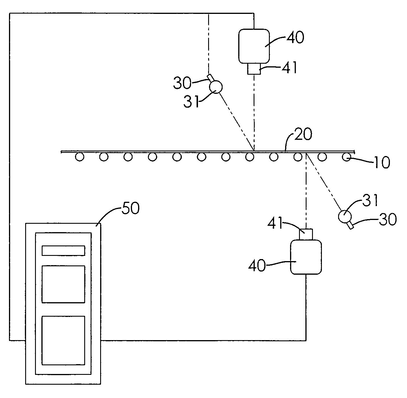
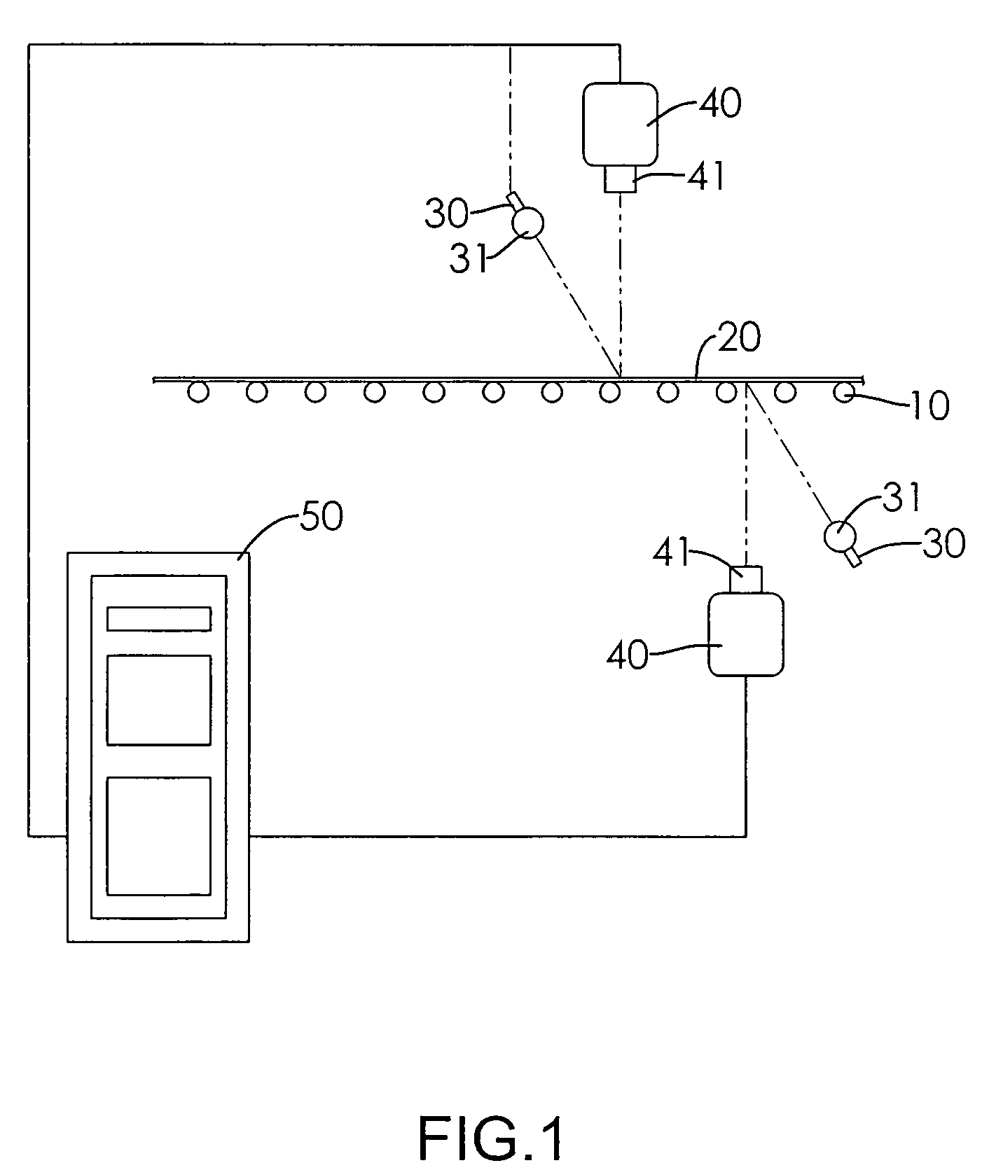
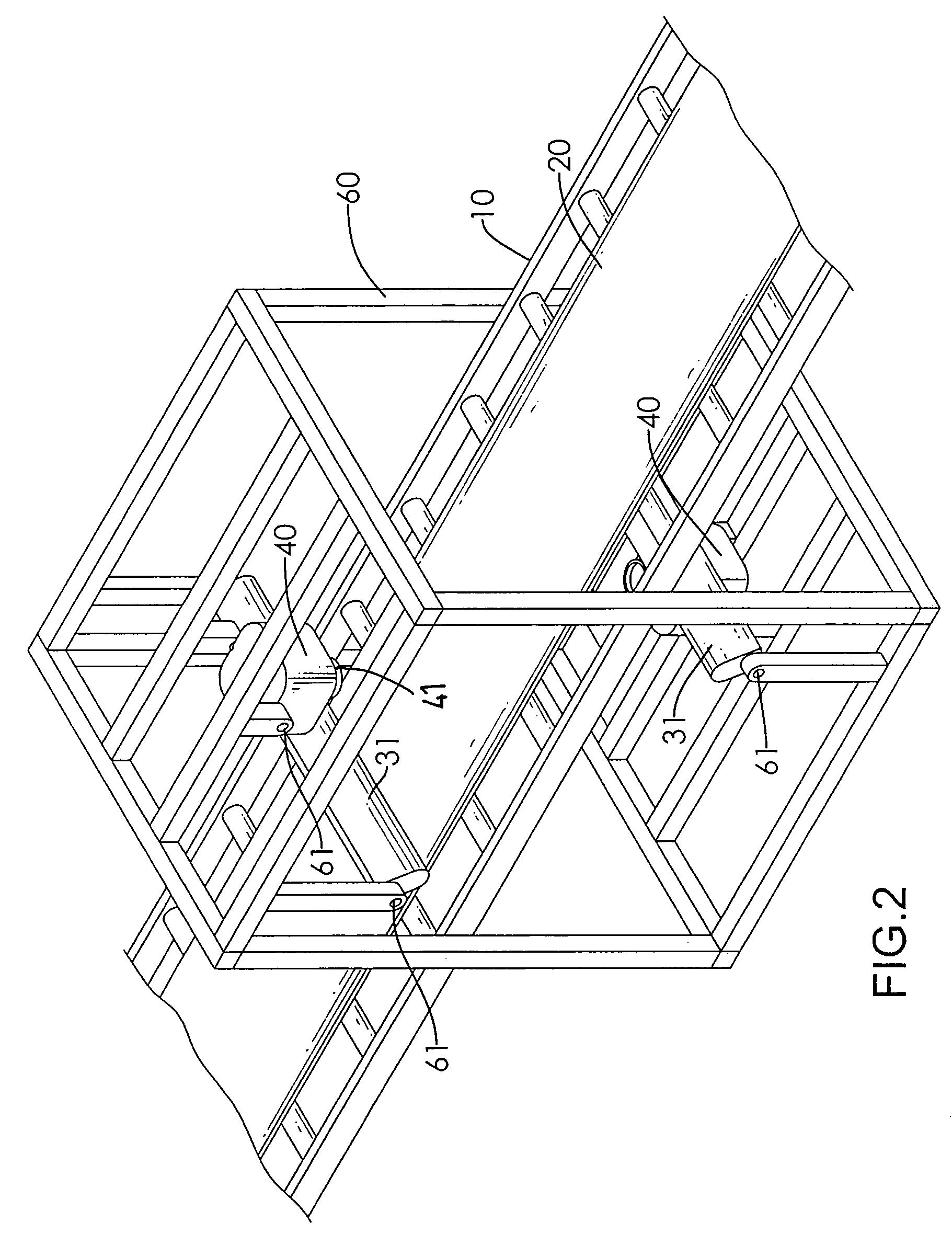
[0017]With reference to FIGS. 1 to 3, substrate-check equipment in accordance with the present invention has a frame (60), a conveyer (10), at least two lamps (30), at least two image acquisition units (40), at least two actuators (70) and a control unit (50).

[0018]The conveyer (10) conveys a substrate and may be pervious to light, mounted through the frame (60) and conveys substrates (20) through the frame (10). The conveyer (10) has an upper surface and a lower surface and may comprise multiple rollers and at least one drive roller, and may further comprise a pervious belt abutting the rollers and being driven to rotate by the at least one driven roller. The rollers are separately disposed along the conveyor perpendicular to a direction of travel and are separated by gaps.

[0019]The lamps (30) are mounted pivotally on the frame (60) using mounting brackets (61) and are mounted respectively above the upper surface of the conveyer (10) and below the lower surface of the conveyer (10)...


PUM

PropertyMeasurementUnit
anglesaaaaaaaaaa
movementaaaaaaaaaa
light intensityaaaaaaaaaa

Abstract

A substrate-check equipment has a conveyer, at least two lamps, at least two image acquisition units and a control unit. The conveyer conveys a substrate. The lamps are mounted respectively above and below the conveyer to respectively shine light onto the substrate. Each lamp has an adjusting unit for adjusting intensity of the lamp. The image acquisition units correspond to the lamps and are mounted respectively above and below the conveyer to respectively capture images of the substrate and generate image signals. The control unit is electronically connected to the lamp and the image acquisition units. Emitted light intensity of the lamps is adjusted to ensure consistent image quality and speed up procedures for checking the substrate.

Description

BACKGROUND OF THE INVENTION[0001]1. Field of Invention[0002]The present invention relates to a substrate-check equipment, and more particularly to a substrate-check equipment that changes light intensity of a lamp to maintain captured image quality and quickly check a substrate.[0003]2. Description of the Related Art[0004]A substrate such as paper, glass, a fabric covered with a layer of resin or multiple layers of fibers formed on a substrate such as paper, glass, a fabric covered by impregnation methods is required to have excellent consistency of parameters for a high-value product.[0005]Generally, a quality of the substrate can be determined by checking upper and lower surfaces of the substrate. A traditional method for checking the upper and the lower surfaces comprises turning over the substrate by operational personnel after checking one of the surfaces, but this wastes timetherefore robotic substrate-check equipment were used to turn over the substrate conveniently.[0006]A c...

Claims


Application Information

Patent Timeline
Patent Type & Authority Patents(United States)
IPC IPC(8): G01N21/00G06K9/00
CPCG01N21/8901G01N2021/8908G01N2201/0624
Inventor LEE, HUI-HSIUNG
Owner RACE AHEAD TECH
Why Eureka
Try Eureka