
Current distributor and protection system for a vehicle

a technology for distributors and vehicles, applied in the direction of contacts, redundant contact pairs, transportation and packaging, etc., can solve the problems of substantial cost increase and cost of electronic fuses

Active Publication Date: 2021-03-16
ROBERT BOSCH GMBH
View PDF16 Cites 3 Cited by
  • Summary
  • Abstract
  • Description
  • Claims
  • Application Information

AI Technical Summary

Benefits of technology

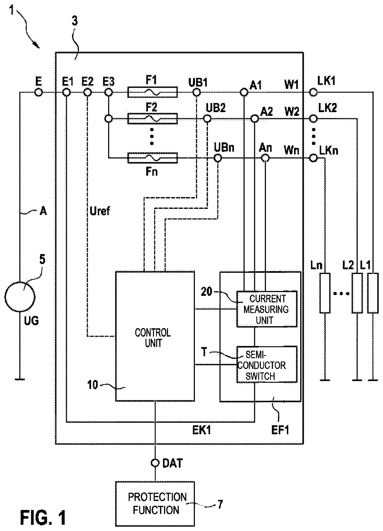
[0004]The current distributor for a vehicle and the protection system for a vehicle have the advantage that each load channel remains permanently wired to an inexpensive conventional fuse as before, wherein in a test mode or in case of a fault a standby channel, protected by an electronic fuse, can be switched in parallel with the load channels protected by safety fuses in order to establish a redundant current path.
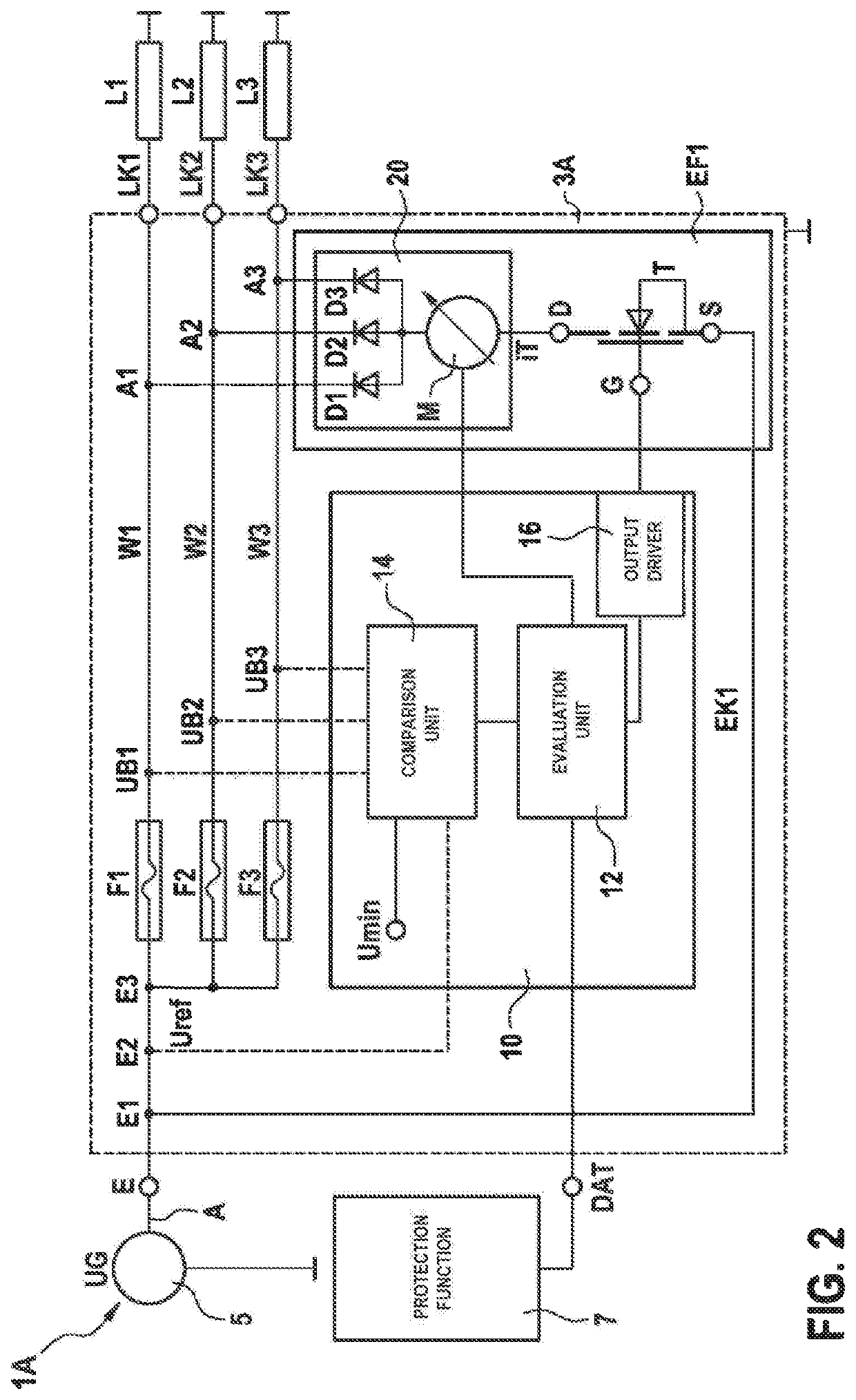
[0017]In another advantageous design of the protection system, the evaluation and control unit can signal a defective safety fuse and / or a defective semiconductor switch to the at least one protection function. In this case, in the event of at least one safety fuse being evaluated as defective, the protection function can switch the evaluation and control circuit into an operating mode in which the evaluation and control unit can monitor the flow of current in the standby channel and maintain the redundant current path through the standby channel or in the overcurrent case, disconnect it. This enables a higher-level protection function to decide whether the subsequent operating mode is allowed, or if the vehicle should be stopped as quickly as possible.

Problems solved by technology

In competition with the technical facilities offered by the electronic fuses are the costs of the electronic fuses, which in comparison to a simple safety fuse represent a substantial cost increase of a factor of 20 to 100 per fuse in the vehicle.

Method used


Image

  • Current distributor and protection system for a vehicle
  • Current distributor and protection system for a vehicle

Examples


Embodiment Construction

[0021]As can be seen from FIGS. 1 and 2 the exemplary embodiments illustrated of protection system 1, 1A according to the invention for a vehicle each comprise a voltage source 5, which provides an on-board power supply voltage UG via a main line A, and a current distributor 3, 3A which applies the on-board power supply voltage UG to a plurality of connected loads L1, L2, L3, Ln.

[0022]As can also be seen from FIGS. 1 and 2, the illustrated examples of a current distributor 3, 3A according to the invention for a vehicle each comprise an input E and a plurality of load channels LK1, LK2, LK3, LKn, which connect the input E to a connected load L1, L2, L3, Ln via a safety fuse F1, F2, F3, Fn and a line W1, W2, W3, Wn in each case. In this case a standby channel EK1 connects the input E to the connected loads L1, L2, L3, Ln via an electronic fuse EF1. An evaluation and control unit 10 monitors the safety fuses F1, F2, F3, Fn for functionality and switches a semiconductor switch T of the ...


PUM


Abstract

A current distributor for a vehicle, having an input and a plurality of load channels which connect the input to a connected load via a safety fuse and a line in each case, and to a protection system for a vehicle having such a current distributor. In this case, a standby channel connects the input to the connected loads via an electronic fuse, wherein an evaluation and control unit checks the safety fuses for functionality and switches on a semiconductor switch of the electronic fuse and forms a redundant current path between the input and the connected loads via the standby channel if at least one of the safety fuses is identified as having been tripped.

Description

[0001]The invention is based on a current distributor for a vehicle and on a protection system for a vehicle.[0002]From the prior art, current distributors for vehicles are known, which have a plurality of load channels, each of which is secured with a safety fuse, and protection systems for vehicles having such a current distributor are known, which instead of safety fuses and relays use integrated semiconductor circuits for implementing electronic protection functions.[0003]Such electronic fuses typically comprise an electronic power switch for connecting and disconnecting an electrical load, as well as elements for implementing protection functions in the event of current overload, overheating, etc. As a rule, in such current distributors all safety fuses are replaced by electronic fuses because the electronic fuses have advantageous properties compared to the safety fuses, such as programmable fusing characteristic curves in the current-time diagram, precise and very fast trippi...

Claims


Application Information

Patent Timeline
Patent Type & Authority Patents(United States)
IPC IPC(8): H02H7/22B60R16/03H01H85/30H02H1/00H01H85/46H01H85/20H01H1/00
CPCH02H7/222B60R16/03H01H85/30H01H85/46H02H1/0007H01H2001/0005H01H2085/208H01H2300/052Y02T10/92
Inventor LANG, THOMAS
Owner ROBERT BOSCH GMBH
Learn More