Surgical targeting systems and methods

a technology of surgical targeting and target image, applied in the field of surgical targeting system and method, can solve the problems of not accurately placing the image in global 3-dimensional space, not providing an accurate location with respect to anatomical landmarks, and the degree of precision desired is still not met using the current methods

Active Publication Date: 2021-03-23
MARKSMAN TARGETING INC
View PDF2 Cites 1 Cited by
  • Summary
  • Abstract
  • Description
  • Claims
  • Application Information

AI Technical Summary

Benefits of technology

[0009]The system comprises an adjustable radiopaque bar marker mounted below external light sources, such as visible light sources or lasers, the associated mounting hardware on the imaging system and a separate targeting guide holder. The mounting hardware allows the radiopaque marker to translate around and across the circumference and face 360° around the image intensifier. The radiopaque bar is able to rotate 90° along the axis parallel to the image intensifier allowing the marker to be effectively radiolucent. Additionally, the radiopaque marker is centered on the intensifier which eliminates the issue of beam divergence. The system is used in conjunction with commonly available preoperative images and commercially available intraoperative radiography equipment. A preoperative image of the intended surgical site is taken using computed tomography (CT) or magnetic resonance Imaging (MRI). It should be noted that the image is already taken to judge the surgical candidacy.
[0011]Prior to the procedure, the light source is mounted to a commercially available radiographic imaging system, such as a fluoroscope or portable x-ray. The light beams are projected as a line onto the skin at the surgical site. The radiopaque bar markers and light sources are located in known positions with respect to the imaging system. The radiopaque bar markers are imaged with the anatomical location of interest, and the light sources are projected onto the skin in the plane of the intended entry point determined in pre- or intraoperative planning. The intersection of two linear light beams in orthogonal planes, typically but not necessarily the anterior / posterior (AP) and medial / lateral (ML) planes, clearly mark the entry point of the surgical instruments on the skin of the patient. The orientation of the surgical instruments at the entry point is set using the target guide holder, an angularly adjustable, bi-planar, mechanical guide to set the angle of the instruments in both orthogonal planes per the pre- or intraoperative plan. The system thereby provides accurate both the positioning coordinates and the orientation of the surgical instrument to the surgeon, such that if the resulting trajectory is followed, the instrument will reach the intended internal surgical site without direct visualization by dissection or repeated radiographic exposures.

Problems solved by technology

It does not accurately place the image in global 3-dimensional space, nor does it provide an accurate location with respect to anatomical landmarks.
Timing is critical, but in the surgeries utilizing today's fluoroscopy systems there is somewhat a hit and miss approach to finding the landmarks need for the attachment of screws for spinal surgery, as the procedure follows a general methodology of measurement and a grid pattern that often does not consider the thickness of a patient's soft tissue and muscle from the area of attachment, such as the pedicles of the spine.
The use of Jamshidi needles, trocars and cannulae for certain surgeries help limit wound size and openings, but the degree of precision desired is still not met using the current methods, even with complex software and robotics.
This increases unnecessary exposure to x-rays and the increased chance of injury to tissue and muscle.
Also, the focus is minimally invasive surgery is to limit the need for opening the body and increase the risk of infection and healing.
While this may be an improvement over opening the entire area of the spine, it still creates issues around infection and healing of the wounds.

Method used


Image

  • Surgical targeting systems and methods
  • Surgical targeting systems and methods
  • Surgical targeting systems and methods

Examples


Embodiment Construction

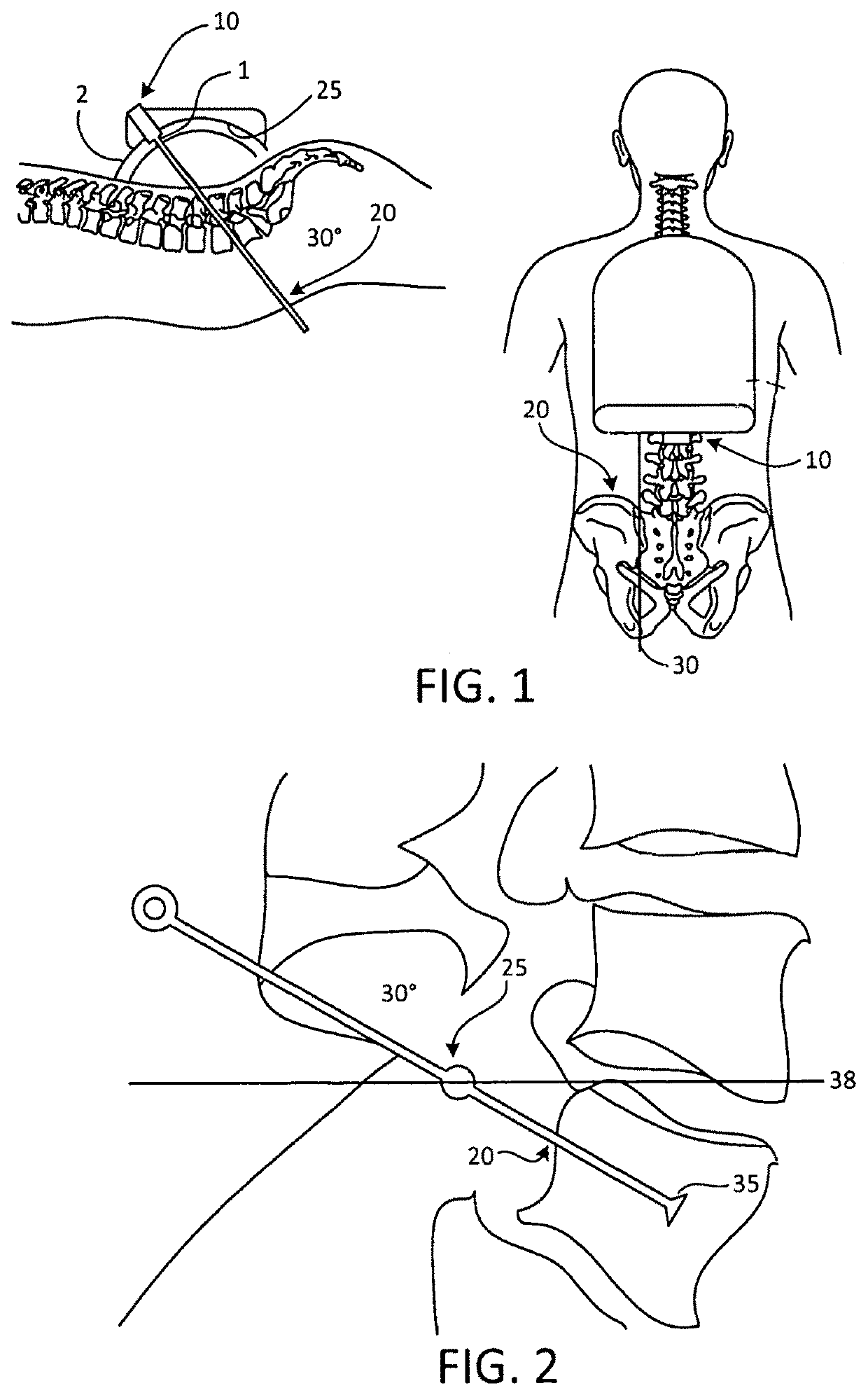
[0047]First, the light source 1 in FIG. 1A must be positioned. A collar system 2 will fit the image intensifier 10 incorporating the light source 1 and the radiopaque marker 25. As shown in FIG. 1A and FIG. 1B, using the radiopaque marker 25 on the face of the laterally positioned image intensifier 10 fluoroscopically the light source trajectory 20 is determined through the spine segment. By superimposing the marker over the anatomy, the system automatically places the laser marker over the skin as shown at 30. This determines both the angle and latitude position on the skin to start the procedure.

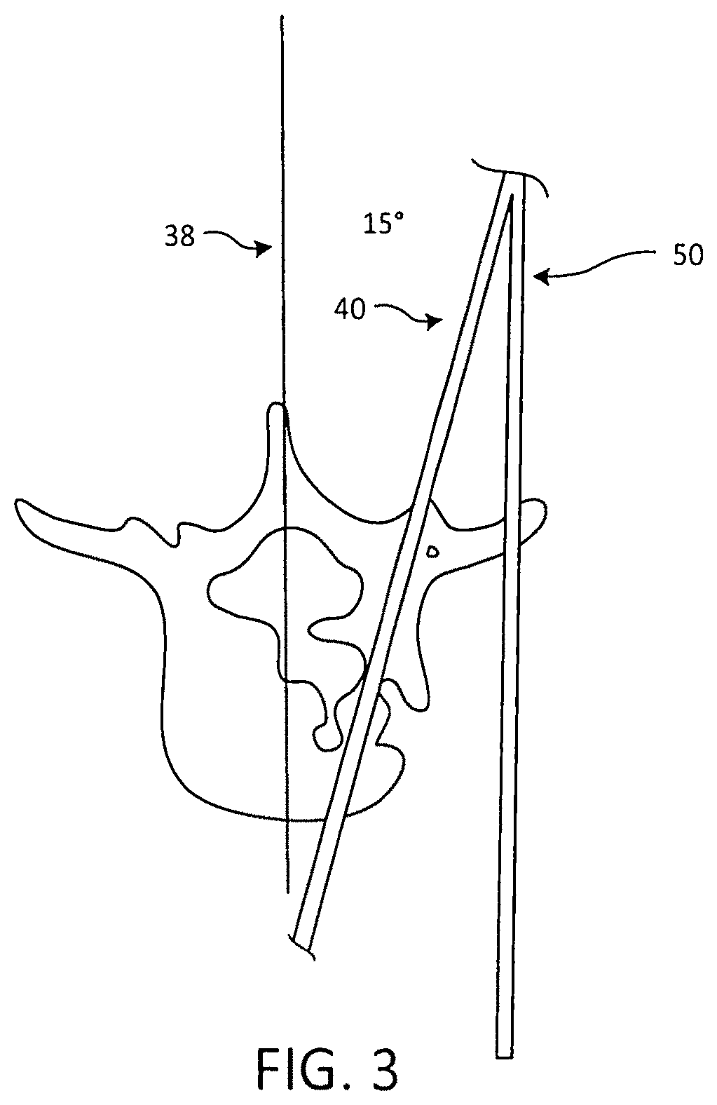
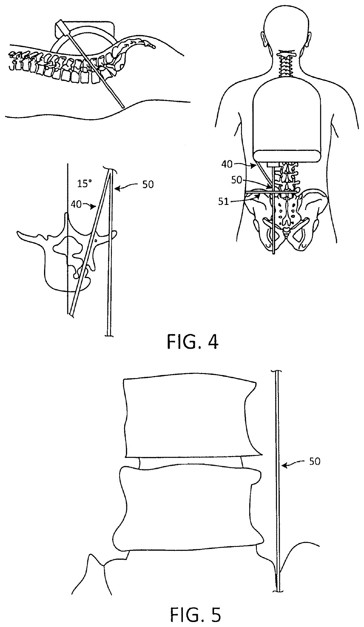
[0048]Next, the A / P position must be determined by looking at the preoperative axial view of the target in question. In FIG. 2, the target in question is a vertebral body 35. The midline 38 is determined, an azimuth through the pedicle or structures desired is positioned, and an angle is determined that would effectively produce the correct trajectory 40 through the anatomy. For example, F...


PUM


Abstract

A medical device having a body having a first bubble vane for measuring angle in one plane; said body having a second bubble vane for measuring an angle in another plane; said first bubble vane having angle indicia; said second bubble vane having angle indicia; said one plane being the in a different plane from said another plane and the angles in the two planes providing the entry point for an incision for the placement of an orthopedic device.

Description

CROSS REFERENCE TO RELATED APPLICATIONS[0001]This application is a continuation in part (CIP) of commonly owned U.S. Ser. No. 14 / 659,497, filed Mar. 16, 2015;[0002]which further claims benefit of U.S. Provisional Ser. No. 61 / 954,250, filed Mar. 17, 2014.BACKGROUNDField of the Invention[0003]The present invention relates to a system and method to aid the placement of surgical devices under radiographic image guidance. More particularly, embodiments of the invention relate to a system utilizing radiopaque markers, an external light source and targets. Light is projected onto the skin or surgical site over a target in conjunction with a radiographic line marker superimposed on a fluoroscopic image to identify bone landmarks and angles so that skin entry points can be identified. This can be augmented by the use of a target system that is held in place by a bedside rail mounted mechanical arm that can hold any position desired. This allows rigid guidance of guide wire to facilitate the ...

Claims


Application Information

Patent Timeline
Patent Type & Authority Patents(United States)
IPC IPC(8): A61B90/11A61B17/17A61B34/20A61B90/00A61B34/10A61B17/34A61B90/13A61B6/02A61B90/30
CPCA61B17/1703A61B17/3472A61B34/10A61B34/20A61B90/11A61B90/13A61B90/37A61B90/39A61B6/02A61B90/30A61B2034/107A61B2034/2051A61B2034/2057A61B2090/067A61B2090/068A61B2090/367A61B2090/374A61B2090/376A61B2090/3764A61B2090/3966A61B2090/3975A61B2090/3983A61B6/4441
Inventor BROWN, ROY ANTHONY
Owner MARKSMAN TARGETING INC
Why Eureka
Try Eureka