Method by which terminal determines beam in wireless communication system and terminal therefor

a wireless communication system and terminal technology, applied in the field of method by which the terminal determines the beam in the wireless communication system, can solve the problem of small service area, and achieve the effect of preventing deterioration of communication quality and minimizing the deformation of communication quality due to the rotation of the terminal

Active Publication Date: 2021-04-13
SAMSUNG ELECTRONICS CO LTD
View PDF8 Cites 1 Cited by
  • Summary
  • Abstract
  • Description
  • Claims
  • Application Information

AI Technical Summary

Benefits of technology

[0017]In a feature of the present invention, when the terminal is rotated, it is possible to rapidly align the direction of the transmission beam and the direction of the reception beam. That is, the time during which the communication quality degrades due to the rotation of the terminal can be minimized.
[0018]In another feature of the present invention, when the terminal is moved, the beam sweeping procedure is performed in advance based on the degree of movement of the terminal, so that deterioration of the communication quality can be prevented.
[0019]Other features or advantages obtainable or predicted from the embodiments of the present invention will be directly or implicitly disclosed in the detailed description. For example, various predicted effects of the embodiments of the present invention will be disclosed within the following detailed description.

Problems solved by technology

However, as it is difficult to obtain an ultra-wideband frequency of 100 MHz or more in frequency bands of several hundred MHz or several GHz used in LTE and LTE-A, the NR system considers transmitting a signal using a wide frequency band existing in frequency bands of 6 GHz or more.
However, as the pathloss of the radio wave is proportional to the frequency, the pathloss of the radio wave is large in such an ultra-high frequency, so that the service area becomes small.

Method used


Image

  • Method by which terminal determines beam in wireless communication system and terminal therefor
  • Method by which terminal determines beam in wireless communication system and terminal therefor
  • Method by which terminal determines beam in wireless communication system and terminal therefor

Examples


Embodiment Construction

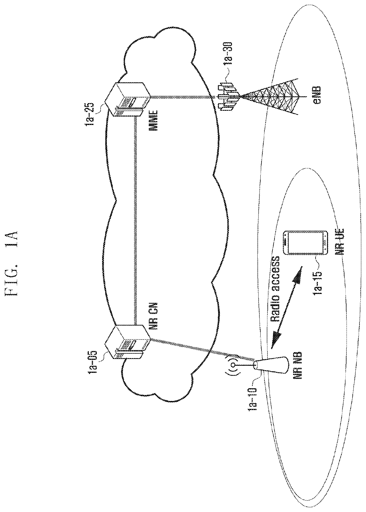
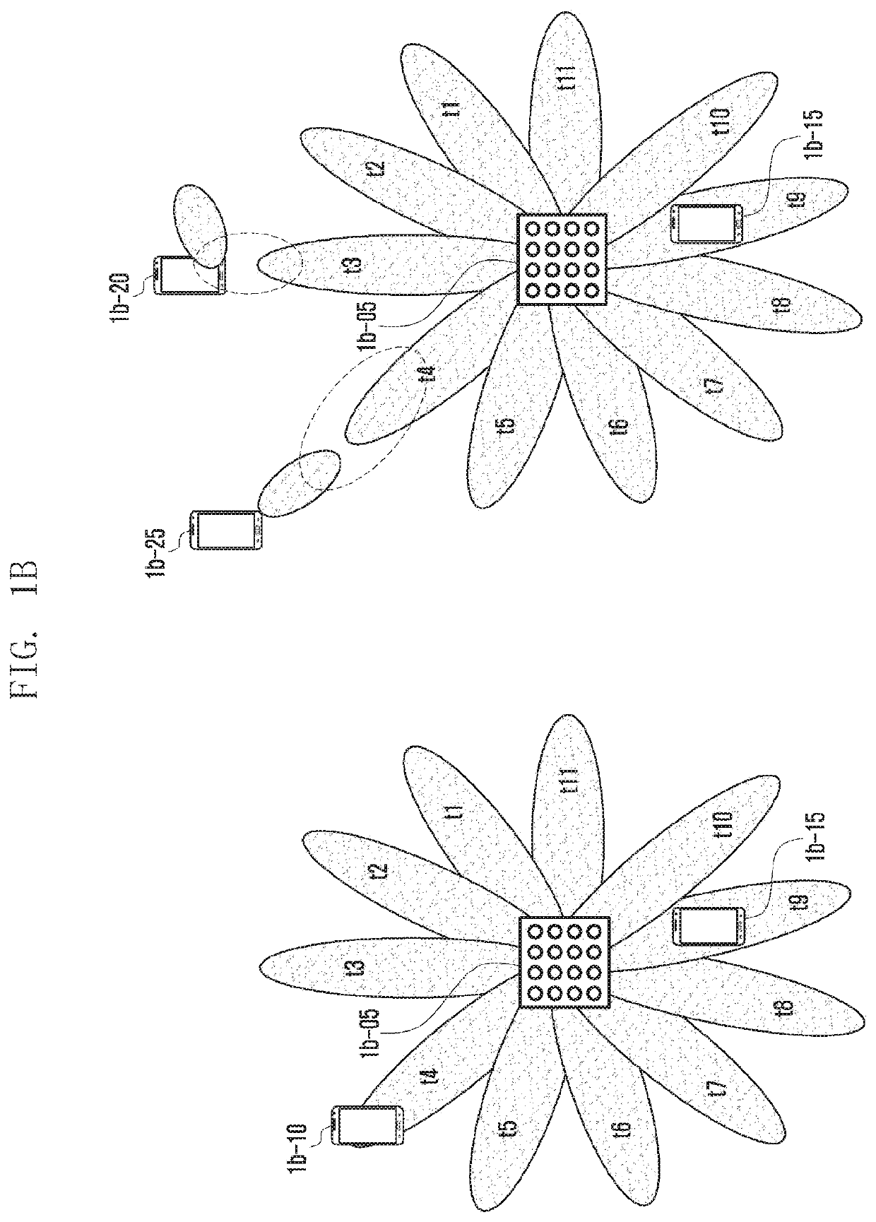
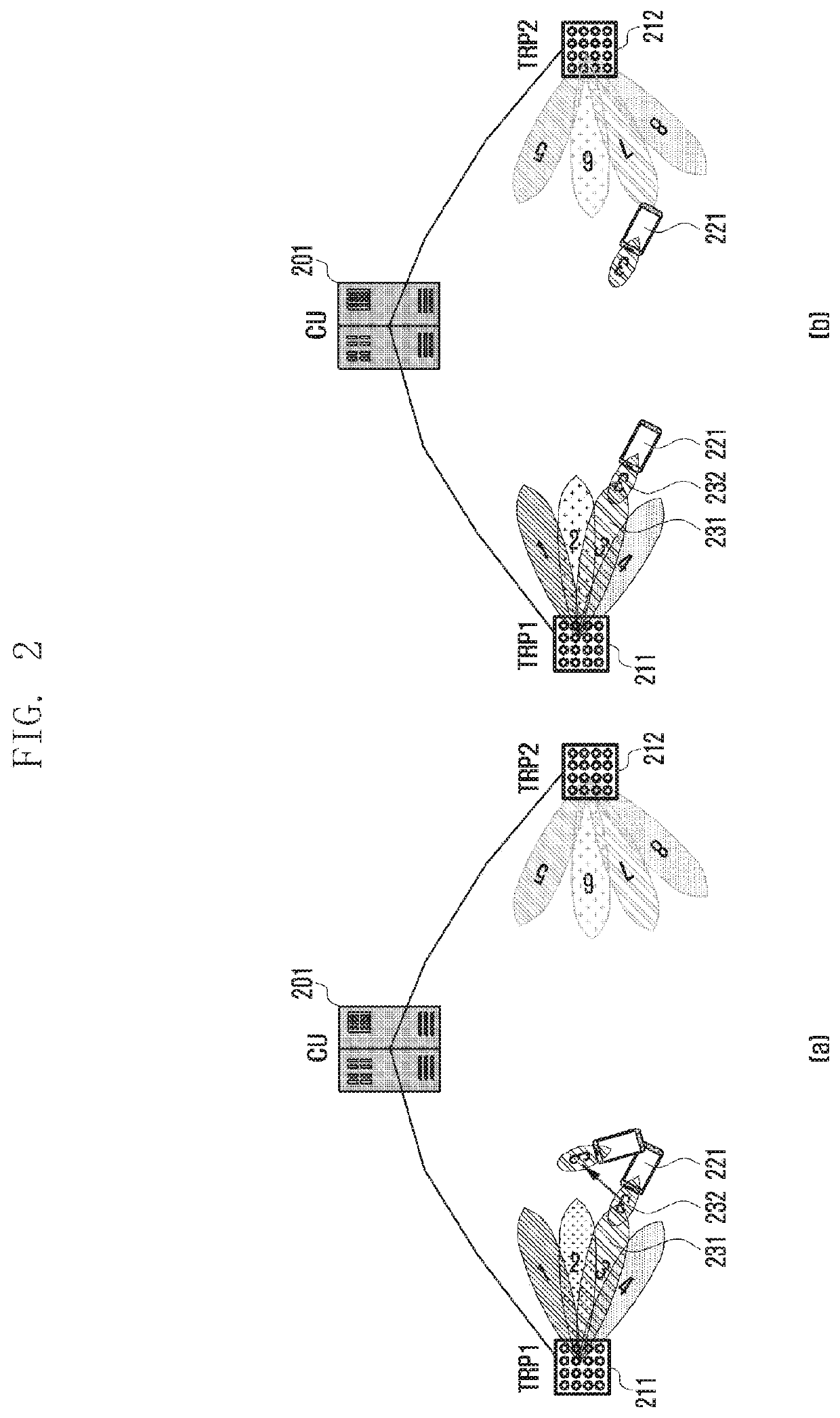
[0030]Hereinafter, embodiments of the present invention are described in detail with reference to the accompanying drawings. The same or similar reference symbols are used throughout the drawings to refer to the same or like parts. Descriptions of well-known functions and structures incorporated herein may be omitted to avoid obscuring the subject matter of the present invention. The terms described below are defined in consideration of their functions in the present invention, and these may vary depending on the intention of the user, the operator, or the custom. Hence, their meanings should be determined based on the overall contents of this specification.

[0031]In the description, the singular forms “a”, “an” and “the” are intended to include the plural forms as well, unless the context clearly indicates otherwise.

[0032]In the description, the terms “1st” or “first” and “2nd” or “second” may use corresponding components regardless of importance or order and are used to distinguish...


PUM


Abstract

The present disclosure relates to a communication method for merging, with IoT technology, a 5G communication system for supporting a data transmission rate higher than that of a 4G system, and a system therefor. The present disclosure can be applied to intelligent services (for example, smart home, smart building, smart city, smart car or connected car, healthcare, digital education, retail business, security and safety related service and the like) on the basis of 5G communication technology and IoT related technologies. The present disclosure relates to a method by which a terminal determines a beam in a wireless communication system, comprising the steps of: performing a beam sweeping procedure of discovering a reception beam of the terminal and a transmission beam of a transmission reception point (TRP) of the wireless communication system, the orienting directions of the reception beam and the transmission beam being aligned to each other; determining a rotation angle of the rotated terminal by using a rotation detection sensor provided to the terminal when the terminal is rotated after the beam sweeping procedure is performed; determining a reception beam on which a downlink signal is to be received on the basis of the determined rotation angle when the determined rotation angle is a predetermined angle or greater.

Description

PRIORITY[0001]This application is a National Phase Entry of PCT International Application No. PCT / KR2017 / 015257 which was filed on Dec. 21, 2017, and claims priority to Korean Patent Application No. 10-2016-0175920, which was filed on Dec. 21, 2016, the content of each of which is incorporated herein by reference.TECHNICAL FIELD[0002]The present invention relates to a terminal and method for the terminal to determine a reception beam for receiving the downlink signal in a wireless communication system.BACKGROUND ART[0003]To meet the demand for wireless data traffic having increased since deployment of 4G communication systems, efforts have been made to develop an improved 5G or pre-5G communication system. Therefore, the 5G or pre-5G communication system is also called a ‘Beyond 4G Network’ or a ‘Post LTE System’. The 5G communication system is considered to be implemented in higher frequency (mmWave) bands, e.g., 60 GHz bands, so as to accomplish higher data rates. To decrease prop...

Claims


Application Information

Patent Timeline
Patent Type & Authority Patents(United States)
IPC IPC(8): H04B7/06H04B7/08H04B7/0408H04B7/0413
CPCH04B7/0695H04B7/0408H04B7/0413H04B7/088
Inventor KIM, SOENGHUN
Owner SAMSUNG ELECTRONICS CO LTD
Why Eureka
Try Eureka