Adjustable grip dual-mating housing structure for removal of a faucet handle to gain access to a corroded valve stem

a dual-mating housing, adjustable grip technology, applied in the direction of metal-working hand tools, manufacturing tools, etc., can solve the problems of faucets which do not enable the removal of faucet handles, and achieve the effect of reducing the chance of sink damag

Active Publication Date: 2021-05-04
EGHBAL MICHAEL
View PDF15 Cites 3 Cited by
  • Summary
  • Abstract
  • Description
  • Claims
  • Application Information

AI Technical Summary

Benefits of technology

[0020]It is an object of the present invention to provide a simple mechanical apparatus for removing a faucet handle from a corroded valve stem in a faucet base by applying a force to remove the faucet handle from a corroded valve stem.
[0021]It is also an object of the present invention to provide adjustable slots and corresponding wing nuts that will allow at least one bottom plate to open and close to allow a faucet handle to be retained above two plates the faucet handle removal process.
[0022]It is an additional object of the present invention to provide a central housing support structure that has two vertical legs that extend to opposite respective horizontal surfaces for transferring the force applied to the faucet handle while it is being removed to a larger surface area of the sink and therefore, reduce the chance of damaging the sink.

Problems solved by technology

A major problem that is addressed by the present invention is that there are numerous faucets which do not enable a faucet handle to be removed to gain access to a faucet valve stem if the valve stem is corroded and needs to be removed from the faucet.
Therefore, for any structure where the sink has a faucet that does not have the axial hole as described above, there are no known ways to remove the handle except by breaking the handle and causing significant damage to the faucet and to the sink assembly.

Method used


Image

  • Adjustable grip dual-mating housing structure for removal of a faucet handle to gain access to a corroded valve stem
  • Adjustable grip dual-mating housing structure for removal of a faucet handle to gain access to a corroded valve stem
  • Adjustable grip dual-mating housing structure for removal of a faucet handle to gain access to a corroded valve stem

Examples


Embodiment Construction

[0039]Although specific embodiments of the present invention will now be described with reference to the drawings, it should be understood that such embodiments are by way of example only and merely illustrative of but a small number of the many possible specific embodiments which can represent applications of the principles of the present invention. Various changes and modifications obvious to one skilled in the art to which the present invention pertains are deemed to be within the spirit, scope and contemplation of the present invention as further defined in the appended claims.

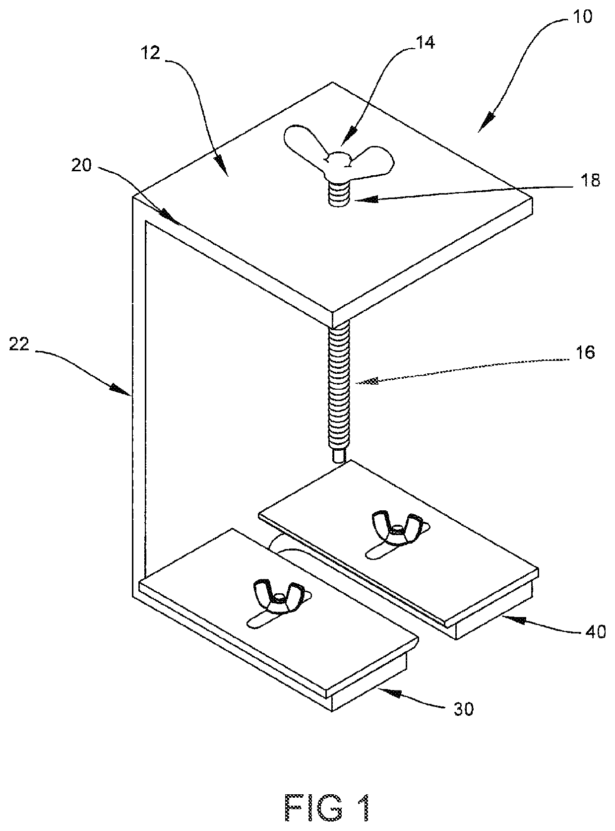
[0040]Referring to FIG. 1, there is illustrated a front perspective view of the screw housing member 10 of the present invention faucet handle remover 100 (illustrated in FIG. 6) illustrating a top wing head 14 that is connected to a top threaded shaft 16 (wing head 14 and threaded shaft 16 may be one piece called a “wing head screw”). Top threaded shaft 16 is sized to fit through top threaded hole 18 loca...


PUM


Abstract

An apparatus for removing a faucet handle that utilizes dual housing mating members for support that prevents the sink from having a direct force placed upon the sink while the apparatus is in use. The apparatus further provides a mating two housing structure having adjustable slots and corresponding wing nuts that will allow a bottom plate to open and close to allow variety of different sized faucet handles to be retained inside of two plates to retain the faucet handle during removal.

Description

BACKGROUND OF THE INVENTION1. Field of the Invention[0001]The present invention relates to the field of replacing a worn out and corroded valve steam of a faucet wherein access to the valve stem is blocked by a portion of the faucet handle.2. Description of the Prior Art[0002]The following eleven patents and published patent applications are the closest prior art known to the inventor.[0003]1. U.S. Pat. No. 2,303,560 issued to Henry J. Knight on Dec. 1, 1942 for “Gear Puller”;[0004]2. U.S. Design Pat. No. 2,870,530 issued to Ervin J, Dvorak on Jun. 27, 1959 for “Faucet Handle Puller”;[0005]3. U.S. Pat. No. 3,334,405 issued to Arthur S. Cann et al. on Aug. 8, 1967 for “Faucet Handle Remover”;[0006]4. U.S. Pat. No. 3,872,569 issued to Lee Lane on Mar. 25, 1975 for “Faucet Handle Remover Tool”;[0007]5. U.S. Pat. No. 5,119,556 issued to Wanlie Hseu on Jun. 9, 1992 for “Tool for Removal of Faucet Stem and Cartridge”;[0008]6. U.S. Pat. No. 5,233,740 to Jui-Nien Chen on Aug. 10, 1993 for “...

Claims


Application Information

Patent Timeline
Patent Type & Authority Patents(United States)
IPC IPC(8): B25B27/24B25B27/02
CPCB25B27/24B25B27/023
Inventor EGHBAL, MICHAEL
Owner EGHBAL MICHAEL
Why Eureka
Try Eureka