Tire

a technology of tires and wheels, applied in the field of tires, can solve the problems of reducing block rigidity, and reducing dry steering stability, and achieve the effect of dry steering stability and on-ice performan

Active Publication Date: 2021-05-04
SUMITOMO RUBBER IND LTD
View PDF11 Cites 2 Cited by
  • Summary
  • Abstract
  • Description
  • Claims
  • Application Information

AI Technical Summary

Benefits of technology

[0004]The present invention was made in view of the above, and a primary object thereof is to provide a tire having both the dry steering stability and the on-ice performance.

Problems solved by technology

However, an increase in the number and length of the sipes causes a decrease in block rigidity, therefore, the dry steering stability and the like are decreased.

Method used


Image

  • Tire
  • Tire
  • Tire

Examples


example

(Working Example)

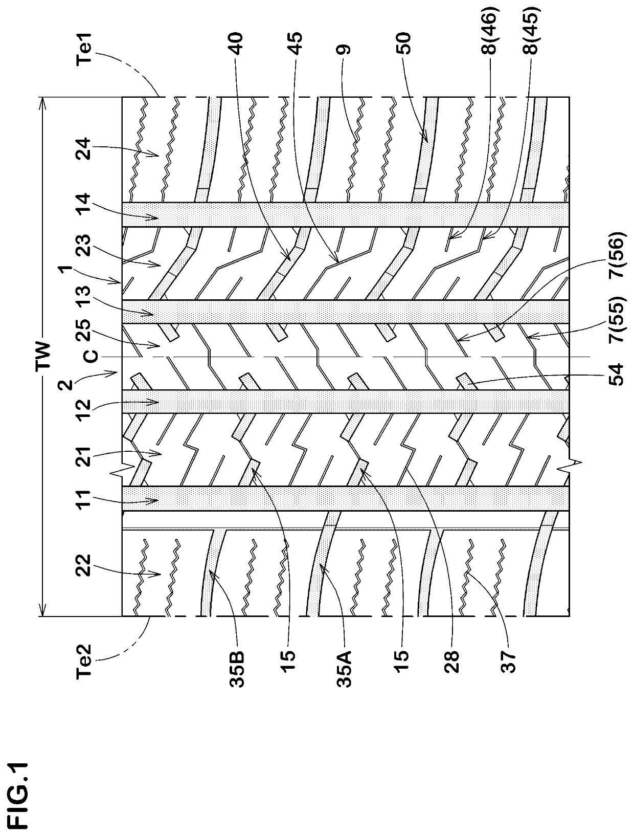
[0119]Tires of size 215 / 60R16 having the basic pattern shown in FIG. 1 were made by way of test according to the specifications listed in Table 1. Each of the test tires was tested for the on-ice performance and the dry steering stability. In Reference 1, the land regions 25 and 23 are provided with oblique sipes extending straight so as to cross the land regions 25 and 23, respectively, at a constant inclination angle. Further, in Examples 11 to 13, the open ends 7E13 and 8E13 are shifted by a half pitch in the tire circumferential direction, and the open ends 8E14 and 9E14 are shifted by a half pitch in the tire circumferential direction, therefore, they don't face each other. Common specifications and the test methods are as follows.

[0120]Tire Rim: 16×6.7

[0121]Tire pressure: 210 kPa

[0122]Test car: front wheel drive car with displacement of 2400 cc

[0123]Tire mounting position: all wheels

[0124]A distance needed for accelerating the above test car from 5 km / h to 20 ...


PUM


Abstract

A tire comprises a center land region 25 provided with center sipes 7 having open ends 7E13 connected with a first center main groove 13 and a first middle land region 23 provided with middle sipes 8 having open ends 8E13 and 8E14 connected with the first center main groove 13 and / or a first shoulder main groove 14. The center sipes 7 include hook-shaped center sipes 55 crossing the center land region 25, and the middle sipes 8 include hook-shaped middle sipes 45 crossing the first middle land region 23.

Description

TECHNICAL FIELD[0001]The present invention relates to a tire having both running performance on a dry road surface (hereinafter referred to as “dry steering stability”) and running performance on an icy road surface (hereinafter referred to as “on-ice performance”).BACKGROUND ART[0002]In a pneumatic tire, a large number of sipes are formed in a tread portion, and the on-ice performance is ensured by frictional force in digging a road surface (edge effect) caused by edges thereof (see Japanese unexamined Patent Application Publication No. 2015-168356, for example).[0003]To increase this on-ice performance, the number and length of the sipes has been increased. However, an increase in the number and length of the sipes causes a decrease in block rigidity, therefore, the dry steering stability and the like are decreased. Thus, there is a trade-off between the on-ice performance and the dry steering stability, and further improvement is required to have both of them at a high level.SUMM...

Claims


Application Information

Patent Timeline
Patent Type & Authority Patents(United States)
IPC IPC(8): B60C11/12B60C11/03
CPCB60C11/1236B60C11/0304B60C11/0306B60C11/1204B60C11/1263B60C2011/0348B60C2011/0351B60C2011/0355B60C2011/0367B60C2011/0369B60C2011/0381B60C2011/1209B60C2011/1213B60C11/042B60C11/1259B60C11/1272B60C11/1307B60C2011/1268B60C2011/1286
Inventor HORIGUCHI, TOSHIKIYAMAOKA, HIROSHI
Owner SUMITOMO RUBBER IND LTD
Why Eureka
Try Eureka