Eureka AIR delivers breakthrough ideas for toughest innovation challenges, trusted by R&D personnel around the world.

Pneumatic tire

a technology of pneumatic tires and treads, which is applied in the direction of tyre tread bands/patterns, vehicle components, transportation and packaging, etc., to achieve the effects of reducing rigidity of tread portions, high independence, and dry performan

Active Publication Date: 2019-10-29
TOYO TIRE & RUBBER CO LTD
View PDF30 Cites 0 Cited by
  • Summary
  • Abstract
  • Description
  • Claims
  • Application Information

AI Technical Summary

Benefits of technology

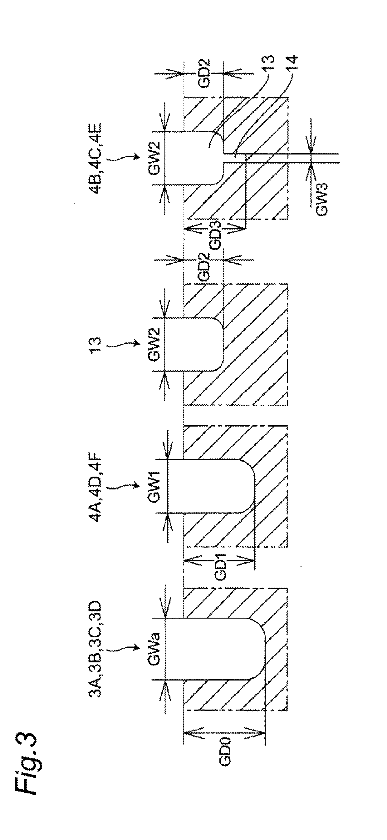
[0110]Firstly, “block” means an island-shaped portion which is separated from the surrounding by the main grooves and the lateral grooves. Assuming that only a plurality of simple blocks are formed on the tread portion 2, each block has high independence and hence, the rigidity of the tread portion is lowered. As a result, dry performance (that is, motion performance such as acceleration, braking and turning on a dry road surface) is also lowered.
[0111]Secondly, to alleviate lowering of dry performance, some “lateral grooves” are replaced with “shallow grooves” so that the rigidity of the tread surface can be increased. However, a snow column shearing force when a vehicle travels on a snowy road is lowered by an amount of groove volume difference caused by the replacement of “lateral grooves” with “shallow grooves” so that snow performance (that is, motion performance such as acceleration, braking and turning on a snowy road) is lowered.
[0112]Thirdly, in the present invention, “shallow groove” is formed on “block”, and “sipe” is formed on a groove bottom of “shallow groove”. That is, “shallow groove with sipes” is formed on “block” (composite block). By forming “sipe” is on the groove bottom of “shallow groove”, compared to a case where the sipe is not formed on the bottom of the shallow groove, the shallow groove can be largely opened and hence, a snow column shearing force can be increased. That is, snow performance can be enhanced.
[0113]The above technical feature can be recapitulated as follows. That is, when only the simple blocks defined by the main grooves and the lateral grooves which are “deep grooves” are formed on the tread portion, the tire has low dry performance. Accordingly, by replacing some “deep groove” with “shallow grooves”, dry performance is increased. On the other hand, snow performance is lowered by an amount of groove volume difference caused by the replacement of “lateral grooves” with “shallow grooves”. To alleviate this lowering of snow performance, “sipe” is additionally formed on a bottom of each “shallow groove”. With such a configuration, the tire can exhibit both excellent snow performance and excellent dry performance.
[0114]As described above, in this embodiment, the outer intermediate row 5D is formed of only composite blocks 21.
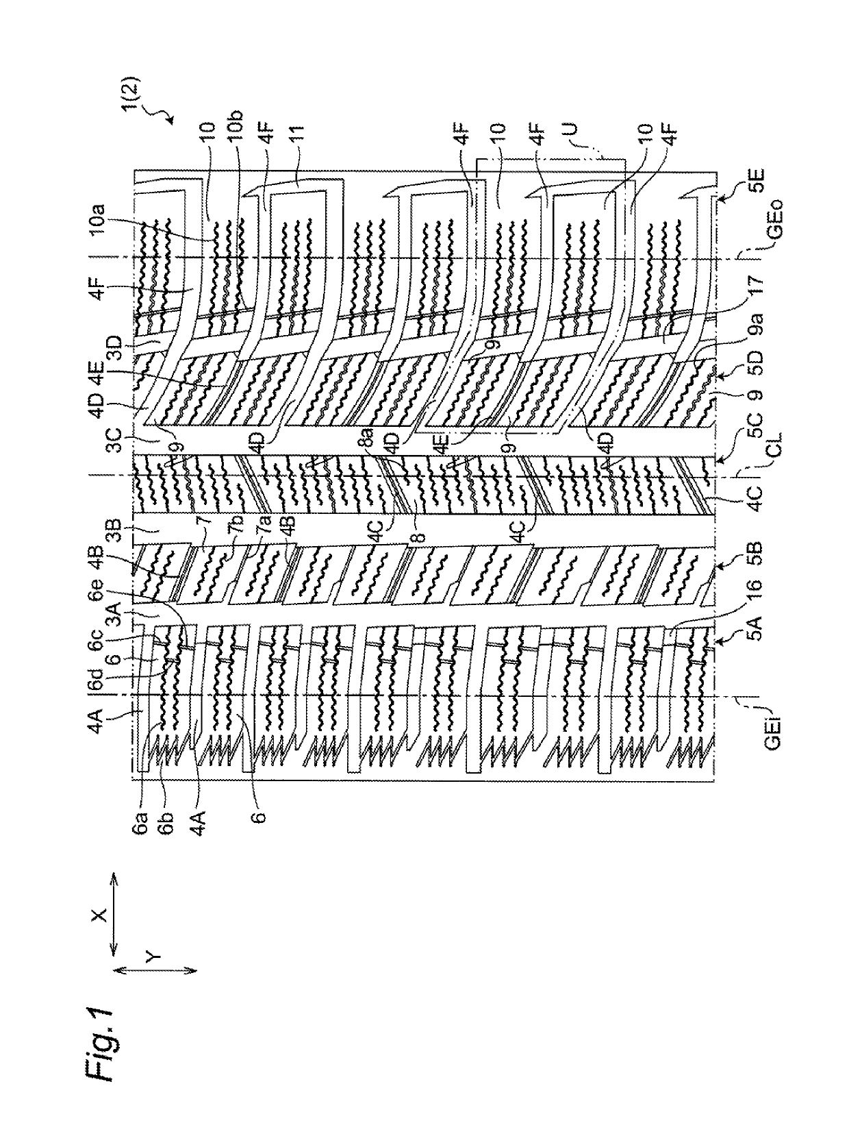
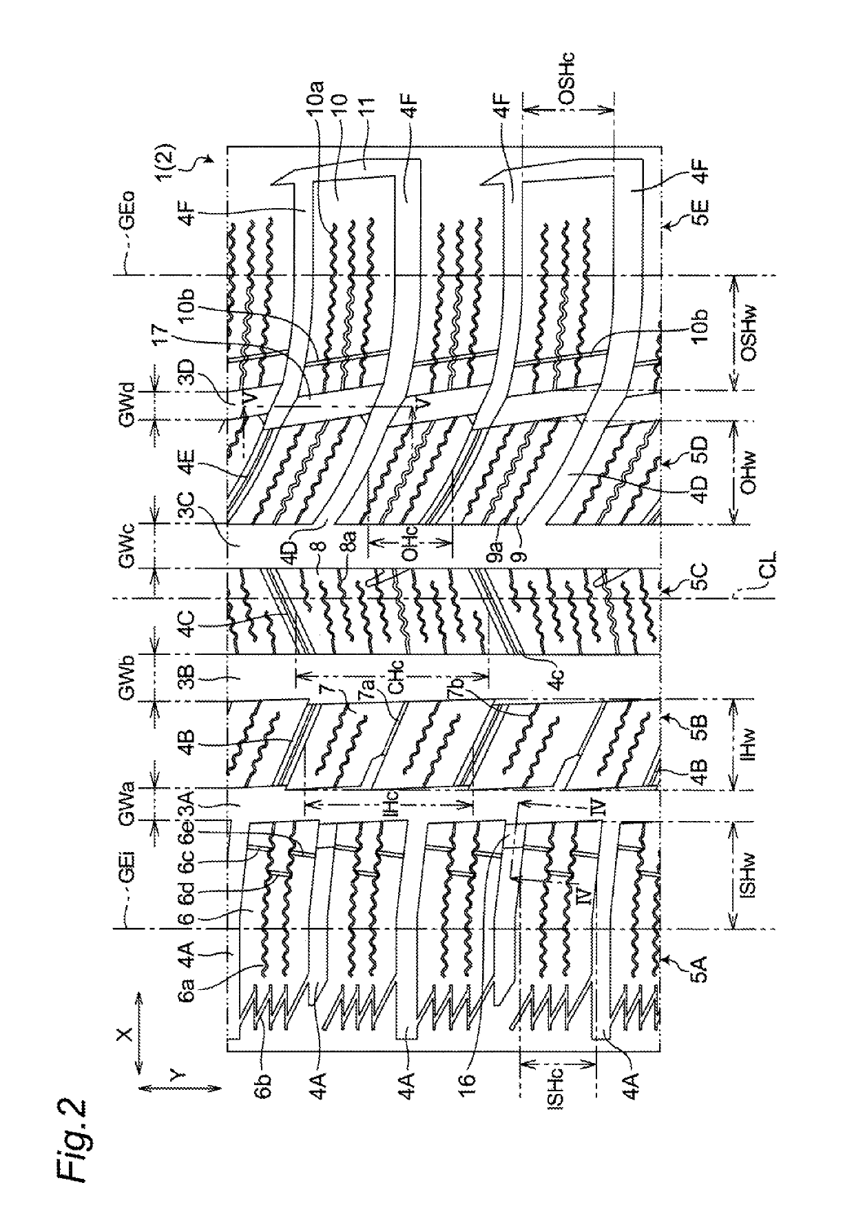
[0115]In this embodiment, each block 6 on the inner shoulder row 5A is simply divided by lateral grooves 4A which are “deep grooves”, and corrugated sipes 6a are formed on a surface of each block 6. In the same manner, each block 10 on the outer shoulder row 5E is simply divided by lateral grooves 4F which are “deep grooves”, and corrugated sipes 10a are formed on a surface of each block 10.

Problems solved by technology

However, it is not always the case with these conventional pneumatic tires that the pneumatic tire has succeeded in enhancing all of the following: drive performance, braking performance and turning performance while ensuring drain performance.

Method used


Image

  • Pneumatic tire
  • Pneumatic tire
  • Pneumatic tire

Examples


second embodiment

[0105]Referring to FIG. 6, on a tread portion 2 of a tire 1 according to a second embodiment, none of inner longitudinal slits 6c, 6d, 6e on an inner shoulder block 6, first raised portions 16, and second raised portions 17 (see also FIG. 1 and FIG. 2 with respect to these constitutional elements) are formed. The same goes for third to seventh embodiments described later with respect to this point.

[0106]On an outer intermediate row 5D disposed between a second center main groove 3C and an outer main groove 3D, a lateral groove 4D which is “deep groove” and a lateral groove 4E which is “shallow groove with sipes” are alternately formed. In the first embodiment, each outer intermediate block 9 which forms the outer intermediate row 5D is defined as a block defined by the second center main groove 3C, the outer main groove 3D, the lateral groove (deep groove) 4D, and the lateral groove (shallow groove with sipes) 4E. However, the lateral groove 4E which is “shallow groove with sipes” h...

third embodiment

[0127]Referring to FIG. 8, a tread portion 2 of a tire 1 according to a third embodiment differs from the tread portion 2 of the tire 1 according to the second embodiment only with respect to the configuration of the inner intermediate row 5B and the center row 5C.

[0128]On the inner intermediate row 5B, a lateral groove 40 which is “deep groove” and a lateral groove 4B which is “shallow groove with sipes” are alternately formed. Accordingly, the inner intermediate row 5B is formed of a plurality of composite blocks 22 each of which is divided by the lateral grooves 4G which are “deep grooves” (see also FIG. 9A).

[0129]In the same manner, on the center row 5C, a lateral groove 4H which is “deep groove” and a lateral groove 4C which is “shallow groove with sipes” are alternately formed. Accordingly, the center row 5C is formed of a plurality of composite blocks 23 each of which is divided by the lateral grooves 4H which are “deep grooves” (see also FIG. 9B).

fourth embodiment

[0130]Referring to FIG. 10, on a tread portion 2 of a tire 1 according to a fourth embodiment, an inner intermediate row 5B, a center row 5C, and an outer intermediate row 5D are formed of only “composite blocks” respectively.

[0131]On the inner intermediate row 5B, two lateral grooves 4B which are “shallow grooves with sipes” are formed between two lateral grooves 4G which are “deep grooves”. One composite block 24 is defined by an inner main groove 3A, a first center main groove 3B, and two lateral grooves 4G which are “deep grooves” (see also FIG. 11A).

[0132]In the same manner, on the center row 5C, two lateral grooves 4C which are “shallow groove with sipes” are formed between two lateral grooves 4H which are “deep grooves”. One composite block 25 is defined by a first center main groove 3B, a second center main groove 3C, and two lateral grooves 4H which are “deep grooves” (see also FIG. 11B).

[0133]On the outer intermediate row 5D, two lateral grooves 4E which are “shallow groov...


PUM


Abstract

Groove widths of center main grooves are larger than groove widths of inner and outer main grooves. Plurality of lateral grooves are formed at intervals in a tire circumferential direction so as to define inner shoulder blocks belonging to an inner shoulder row. A first raised portion connecting a pair of inner shoulder blocks to each other is formed in the lateral grooves every one other on an inner main groove side. A depth of the lateral groove in the first raised portion is smaller than the depth of the lateral groove in other portions. A second raised portion is formed on the outer main groove in a region defined by an imaginary line connecting an outer intermediate block and an outer shoulder block. A depth of the outer main groove in the second raised portion is smaller than that of the outer main groove in other portions.

Description

CROSS-REFERENCE TO RELATED APPLICATIONS[0001]This application claims priority of Japanese Patent Application Nos.: 2015-198703, 2015-198704, and 2015-198707 filed on Oct. 6, 2015, the contents of which are incorporated herein by reference.BACKGROUND OF THE INVENTION[0002]Technical Field[0003]The present invention relates to a pneumatic tire.[0004]Related Art[0005]WO 2012 / 111589, Japanese Patent 5639461, Japanese Patent 3376342 and JP 2012-96782 A disclose a pneumatic tire having a plurality of block rows extending in a tire circumferential direction. Each block row has a plurality of blocks arranged in a row in the tire circumferential direction. However, it is not always the case with these conventional pneumatic tires that the pneumatic tire has succeeded in enhancing all of the following: drive performance, braking performance and turning performance while ensuring drain performance.[0006]There have been proposed tires having various tread patterns for the purpose of enhancing mo...

Claims


Application Information

Patent Timeline
Patent Type & Authority Patents(United States)
IPC IPC(8): B60C11/13B60C11/03B60C11/12
CPCB60C11/0309B60C11/0306B60C11/1272B60C11/125B60C11/0302B60C11/0304B60C11/1369B60C11/1259B60C2011/0367B60C2011/0353B60C2011/0369B60C2011/1213B60C2011/0341B60C2011/0388B60C2011/0355B60C11/03B60C2011/0358B60C2011/0346B60C2011/0381B60C2011/0374
Inventor TANIGUCHI, JIRO
Owner TOYO TIRE & RUBBER CO LTD
Why Eureka
Eureka Blog
Learn More