Tire

a technology of tires and wheels, applied in the field of tires, can solve the problems of unsatisfactory traveling performance and achieve the effect of uneven wear resistance and excellent wet performan

Active Publication Date: 2021-06-01
SUMITOMO RUBBER IND LTD
View PDF18 Cites 0 Cited by
  • Summary
  • Abstract
  • Description
  • Claims
  • Application Information

AI Technical Summary

Benefits of technology

[0004]The present disclosure has been made by taking the problem as mentioned above into consideration, and a main object of the present disclosure is to provide a tire capable of exerting an excellent wet performance while maintaining a dry grip performance and an uneven wear resistance when traveling under severe cornering force in racing circuits.

Problems solved by technology

Unfortunately, the tire disclosed in the Patent Literature 1 has a problem that a satisfactory traveling performance cannot be obtained, for example, in racing circuits traveling in a wet state.

Method used


Image

  • Tire
  • Tire
  • Tire

Examples


examples

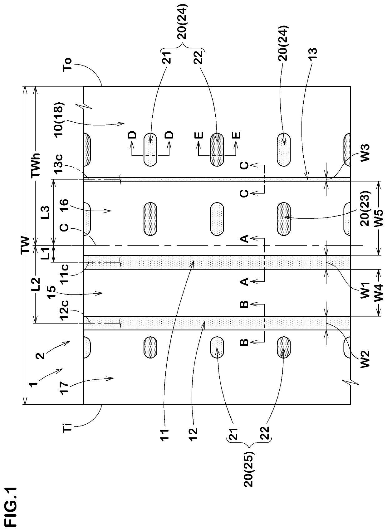
[0098]Pneumatic tires 235 / 40R18 with a basic tread pattern as shown in FIG. 1 were manufactured by way of trial on the basis of the specification in Table 1. A tire provided with no closed groove was manufactured by way of trial as illustrated in FIG. 7, as a comparative example. The tire according to the comparative example was substantially the same as the tire with the tread pattern in FIG. 1 except a point that the closed grooves are not provided. Lap time on a dry road surface, generating speed of hydroplaning phenomenon and uneven wear resistance were tested in each test tire. The common specification and the testing method of the test tires are as follows.

[0099]Rim: 18×8.5 J

[0100]Tire internal pressure: 180 kPa

[0101]Test vehicle: engine displacement 2,500 cc, four-wheel drive vehicle

[0102]Tread half width TWh=105.0 mm

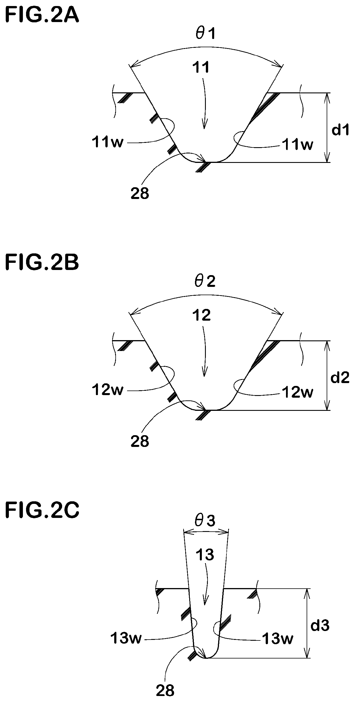
[0103]Groove widths W1 and W2 of first and second main grooves: 10.0 mm

[0104]Groove width W3 of third main groove: 3.0 mm

[0105]Groove depths of main grooves: 5.5...


PUM


Abstract

A tire includes a tread portion including first to third main grooves continuously extending in a tire circumferential direction. The first main groove has a groove centerline arranged on a side of the inboard tread edge with respect to a tire equator and the groove centerline is located at an axial distance L1 from the tire equator of from 5% to 25% of a tread half width. The second main groove is arranged between the first main groove and the inboard tread edge and has a groove centerline located at an axial distance L2 from the tire equator of from 35% to 65% of the tread half width. The third main groove is arranged between the tire equator and the outboard tread edge and has a groove centerline located at an axial distance L3 from the tire equator of from 25% to 55% of the tread half width.

Description

BACKGROUND ARTField of the Disclosure[0001]The present disclosure relates to a tire, and more particularly to a tire capable of exerting an excellent performance when traveling under severe cornering force in racing circuits.Description of the Related Art[0002]Japanese Patent No. 6055521 discloses a tire which is mainly used for traveling under severe cornering force in racing circuits. The tire is provided with a main groove which continuously extends in a tire circumferential direction only on an inboard tread portion which is to be positioned in an inboard of a vehicle when being installed to the vehicle.[0003]Unfortunately, the tire disclosed in the Patent Literature 1 has a problem that a satisfactory traveling performance cannot be obtained, for example, in racing circuits traveling in a wet state.SUMMARY OF THE DISCLOSURE[0004]The present disclosure has been made by taking the problem as mentioned above into consideration, and a main object of the present disclosure is to pro...

Claims


Application Information

Patent Timeline
Patent Type & Authority Patents(United States)
IPC IPC(8): B60C11/04B60C11/117B60C11/03B60C11/13
CPCB60C11/04B60C11/032B60C11/0304B60C11/042B60C11/1307B60C2011/0348B60C2011/0353B60C2011/0355B60C2011/0362B60C2011/0365B60C2011/0367B60C2011/0381B60C2011/0383B60C2200/04B60C11/03B60C11/1236B60C11/1272B60C2011/0341B60C2011/1286Y02T10/86
Inventor MAEDA, YOSHIYUKINAKANO, KEITA
Owner SUMITOMO RUBBER IND LTD
Why Eureka
Try Eureka