

Pneumatic tire
A technology for pneumatic tires and tires, which is applied to tire parts, tire treads/tread patterns, transportation and packaging, etc., to achieve the effects of suppressing air column resonance, improving noise performance, and improving wet road performance
Active Publication Date: 2014-10-15
SUMITOMO RUBBER IND LTD
View PDF5 Cites 5 Cited by
- Summary
- Abstract
- Description
- Claims
- Application Information
AI Technical Summary
Problems solved by technology
However, even with such a pneumatic tire, there is room for further improvement in terms of both wet performance and noise performance
Method used
View moreImage
Smart ImageViewing Examples

Examples
Embodiment
[0094] Based on the specifications in Table 1, a trial production withfigure 1 The size of the basic pattern is 165 / 70R14 pneumatic tires. In addition, wet performance, noise performance, wear resistance, and lateral resistance were tested for each of the trial-produced tires. The common specifications of each tire are as follows.
[0095] Mounting rim: 14×5J
[0096] Tire internal pressure: 230kPa
Login to View More PUM
| Property | Measurement | Unit |
|---|---|---|
| Sliding angle | aaaaa | aaaaa |
Abstract
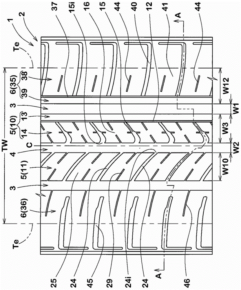
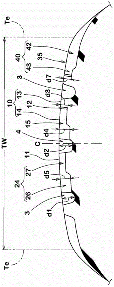
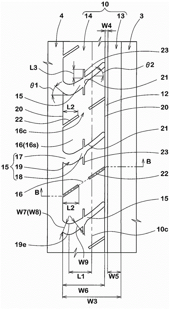
The present invention relates to a pneumatic tire that exhibits excellent noise performance while maintaining wet performance. Each of the shoulder and center grooves (3, 4) has a groove width (TW) set in range of 7 to 9% of width of the tread footprint. Middle land sections (5) include an outer middle land portion (10) divided by a middle narrow groove (12) into a first outer middle land portion (13) and a second outer middle land portion (14). The first outer middle land portion is bar-shaped. A plurality of outer side cross trenches (15) are arranged on the second outer middle land portion (14). Each of outer middle lateral grooves (15) includes a first portion (17) and a second portion (18) having the opposite inclination to the inclination of the first portion (17), and a connection portion (19) between the first portion (17) and the second portion (18). The connection portion (19) is positioned on a center main groove (4) side with respect to the center point of the outer middle land portion (10) in the tire axial direction.
Description
technical field [0001] The present invention relates to a pneumatic tire that maintains wet performance and improves noise performance. Background technique [0002] A main groove extending continuously in the tire circumferential direction is provided on a tread portion of a pneumatic tire. Such main grooves improve the wet performance of the tire. [0003] However, the main groove generates undesired noise (mainly air column resonance sound) during running, thus reducing the noise performance of the tire. In particular, the main grooves connected with the transverse grooves extending axially along the tire will produce a greater air column resonance sound. Therefore, tires having both wet road performance and noise performance are required. [0004] For example, Patent Document 1 below proposes a pneumatic tire that improves wet performance and noise performance while suppressing deterioration of dry road performance based on determining rigidity of shoulder land portio...
Claims
Login to View More Application Information
Patent Timeline
 IPC IPC(8): B60C11/117B60C11/113
CPCB60C11/1236B60C11/0302B60C2011/0369B60C2011/0381B60C11/0306B60C2011/1209B60C11/0304B60C2011/036B60C2011/0348B60C2011/0351B60C2011/0393
Inventor末野顺也
OwnerSUMITOMO RUBBER IND LTD