
Particulate material haulage arrangement

a technology for hauling arrangements and particles, which is applied in the direction of transportation items, large containers, containers, etc., can solve the problems of material remaining, insufficient control of the ejection of material from the tray, damage to the tray, etc., and achieve the effect of reducing the dynamic friction of the floor

Active Publication Date: 2021-05-11
629 032 373 PTY LTD
View PDF12 Cites 1 Cited by
  • Summary
  • Abstract
  • Description
  • Claims
  • Application Information

AI Technical Summary

Benefits of technology

[0021]In a further embodiment, the floor is substantially suspended between the side walls and above the frame to minimise impact damage to the floor from incoming particulate material.
[0024]In one example, the lower section of the frame is configured to reduce dynamic friction of the floor sliding across said lower section.
[0045]In a further embodiment, the floor is substantially suspended between the side walls and above the frame to minimise impact damage to the floor from incoming particulate material.
[0048]In one example, the lower section of the frame is configured to reduce dynamic friction of the floor sliding across said lower section.

Problems solved by technology

There are shortcomings in the prior art, as berm contact of tipping trays can result in damage to the tray, and the ejection of material from the tray is not sufficiently controllable.
In addition, particulate material may adhere to the tray, resulting in so-called ‘carry-back’, where adhesion and / or cohesion between the material particles and the tray results in material that remains in the tray.
Such carry-back wastes tray volume as material is carried back and forth and often requires manual removal, adding time, cost and risk to haulage operations.
These known systems are prone to malfunction due to complexity, do not sufficiently address carry-back and are generally unable to cater for different types of particulate material, in particular heavier loads such as iron ore, or the like.

Method used


Image

  • Particulate material haulage arrangement
  • Particulate material haulage arrangement
  • Particulate material haulage arrangement

Examples


Embodiment Construction

[0075]Further features of the present invention are more fully described in the following description of several non-limiting embodiments thereof. This description is included solely for the purposes of exemplifying the present invention to the skilled addressee. It should not be understood as a restriction on the broad summary, disclosure or description of the invention as set out above. In the figures, incorporated to illustrate features of the example embodiment or embodiments, like reference numerals are used to identify like parts throughout.

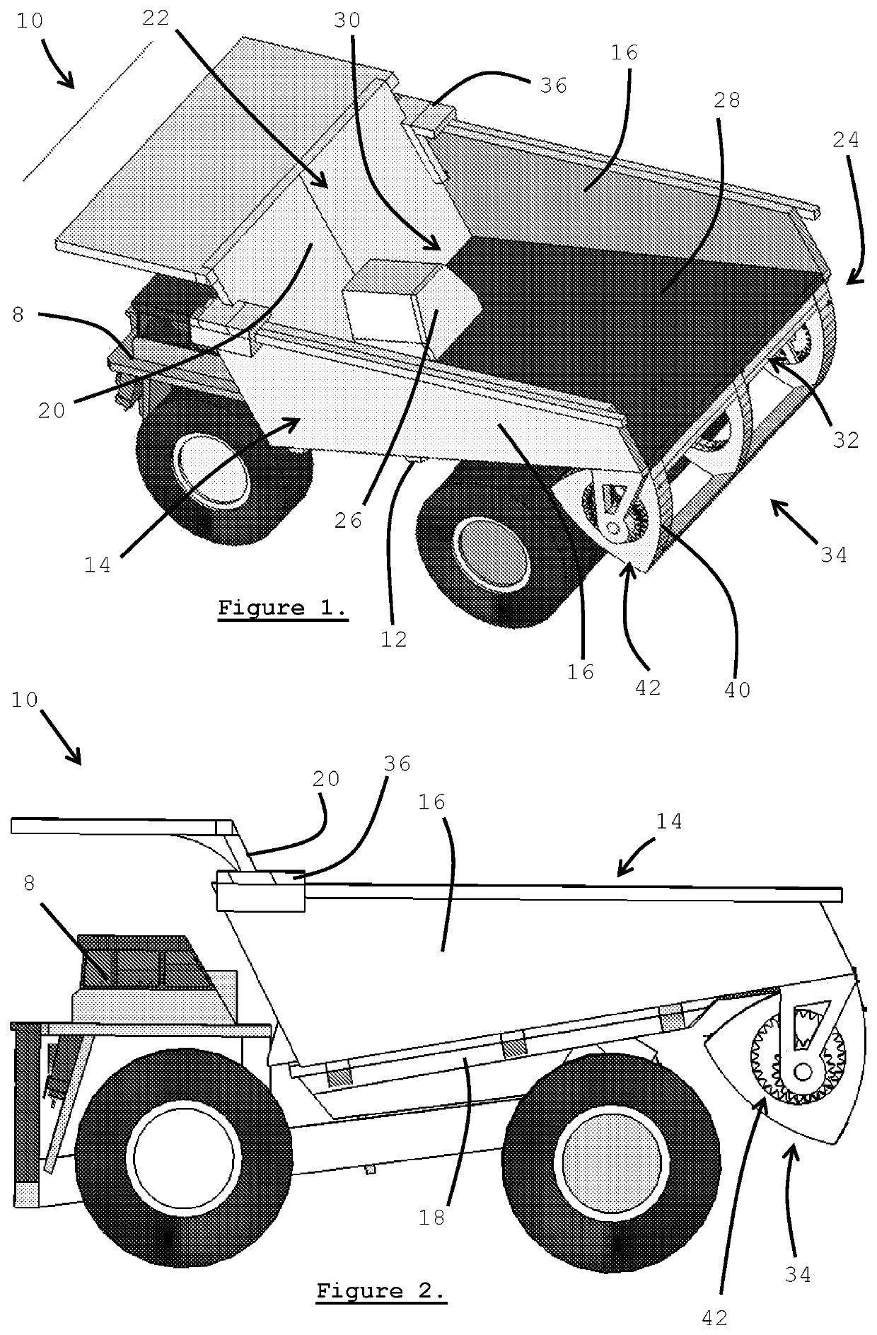
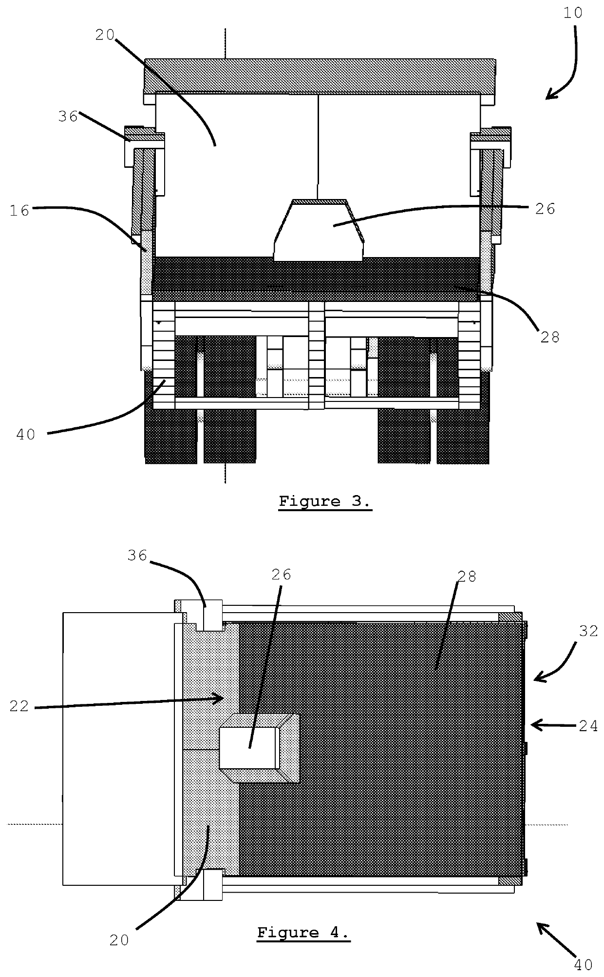
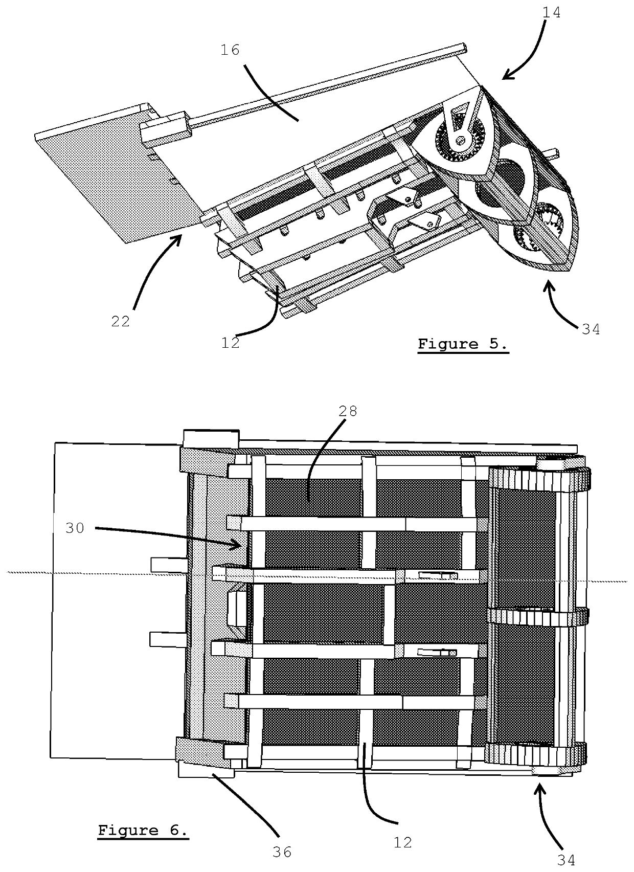
[0076]With reference now to the accompanying Figures, there is shown one possible example of a particulate material haulage arrangement 10. In this embodiment, the haulage arrangement 10 generally comprises a frame 12 configured for operative attachment to a suitable tractor 8, such as a haulage truck typically used in mining, albeit manned or automated. However, other tractors are apposite and may include tractors, trucks, locomotives, mar...


PUM


Abstract

A haulage arrangement has a frame configured for operative attachment to a suitable tractor, and defining a tray for operatively receiving particulate material therein. The tray comprises two side walls separated by a loadbearing lower section with a headwall at a head end of the tray and slidably arranged in-between the side walls. Also included is an urger at the head end configured to operatively urge the headwall to slide across the lower section. Arrangement further includes an elastically flexible floor slidably arranged on the lower section and fast at a first end with the headwall, as well as a retractor arranged at an ejection end of the tray and configured to continuously retract a second end of the floor underneath the lower section whilst the headwall is urged. The retractor is further configured to agitate the floor during retraction to counteract adhesion of particulate material ejected from the tray.

Description

TECHNICAL FIELD[0001]This invention relates to a particulate material haulage arrangement, a haulage truck for particulate material, and an associated method for hauling particulate material.BACKGROUND ART[0002]The following discussion of the background art is intended to facilitate an understanding of the present invention only. The discussion is not an acknowledgement or admission that any of the material referred to is or was part of the common general knowledge as at the priority date of the application.[0003]Transport of particulate material is known in the art. Various arrangements are known whereby particulate material is loaded and unloaded from carriers or similar haulage arrangements. A typical example includes dump trucks having trays and / or trailer arrangements for transporting particulate material. Material is typically loaded into a dump truck by means of a front-end loader, excavator or a suitable hopper or loading silo, and then transported to a desired location, whe...

Claims


Application Information

Patent Timeline
Patent Type & Authority Patents(United States)
IPC IPC(8): B60P1/38B60P1/00B60P1/16B60P1/36B65D88/60
CPCB60P1/006B60P1/38B60P1/16B60P1/365B65D88/60B65G2814/032
Inventor ORLOV, DENIS
Owner 629 032 373 PTY LTD
Learn More