Engine diagnostic system and engine diagnosing method

a technology for engine diagnostics and diagnostic systems, applied in the direction of machines/engines, electrical control, mechanical equipment, etc., can solve the problems of engine deterioration, engine deterioration, and engine deterioration gradually, so as to reduce engine knocking

Active Publication Date: 2021-05-11
TOYOTA JIDOSHA KK
View PDF1 Cites 0 Cited by
  • Summary
  • Abstract
  • Description
  • Claims
  • Application Information

AI Technical Summary

Benefits of technology

[0006]Example 1: An engine diagnostic system that diagnoses a deterioration degree of an engine is provided. The engine is mounted on a vehicle. The engine diagnostic system is configured to learn, as a knock learning value, a maximum advancement amount of an ignition timing that reduces knocking of the engine. The engine diagnostic system includes a database, which is configured to store time-series data of the knock learning value of the engine for each individual engine. The knock learning value is acquired from each of a plurality of vehicles of the same model. The engine diagnostic system is configured to execute an evaluation process, which computes an evaluation value indicating the deterioration degree of a designated engine using the time-series data of the knock learning value of each engine stored in the database.
[0007]The database of the engine diagnostic system collects the time-series data of the knock learning value from multiple engines mounted on the vehicles of the same model. The time-series data of the knock learning value of the engine to be diagnosed is compared with those of other engines. This enables the evaluation of the deterioration degree of the engine relative to other engines. Thus, in the evaluation process of the above-described engine diagnostic system, the following evaluation value is obtained without setting the criterion used in evaluating the deterioration degree. That is, the evaluation value indicating the deterioration degree of the engine to be diagnosed is computed as a value showing the evaluation relative to the engines, the time-series data of the knock learning value of each of which is stored in the database. Also, the change in the knock learning value over time from the initial value can be tracked in the time-series data. Thus, even if there are individual differences in the initial value of the knock learning value among the engines, the deterioration degree of the engine is properly diagnosed using the knock learning value. Thus, the above-described engine diagnostic system is capable of properly diagnosing the deterioration degree of the engine using the knock learning value.
[0009]In some cases, the knock resistance of the engine changes greatly depending on the type of fuel used. In such a case, if the data of the knock learning value learned when different types of fuel are used is mixed in the time-series data collected in the database, the deterioration degree of the engine may possibly fail to be diagnosed properly. Such mixing of the knock learning value learned when different types of fuel is used in the time-series data is avoided by the following configuration of the above-described engine diagnostic system. That is, in Example 2, the engine diagnostic system of Example 1 may be configured such that: the engine diagnostic system is configured to acquire, from the vehicle, fuel-type information of fuel used in the engine when the knock learning value is learned together with the knock learning value; and the engine diagnostic system is configured to store, in the database, only the time-series data of the knock learning value learned when a specific type of fuel is being used. With this configuration, the knock learning value learned when different types of fuel are used is prevented from being mixed in the time-series data. Also, in Example 3, the engine diagnostic system of Example 1 may be configured such that: the engine diagnostic system is configured to execute a fuel determination process, which determines a type of fuel used in the engine when the knock learning value is learned; and the engine diagnostic system is configured to store, in the database, only the time-series data of the knock learning value learned when a specific type of fuel is being used. This also prevents the knock learning value learned when different types of fuel are used from being mixed in the time-series data. Further, in Example 4, the engine diagnostic system of Example 1 may be configured such that: the engine diagnostic system is configured to execute a fuel determination process, which determines a type of fuel used in the engine when the knock learning value is learned; and the engine diagnostic system is configured to store the time-series data of the knock learning value in the database and to compute the evaluation value in the evaluation process separately for each type of fuel. With this configuration also, the knock learning value learned when different types of fuel are used is prevented from being mixed in the time-series data.
[0012]Example 7: An engine diagnosing method for diagnosing a deterioration degree of an engine mounted on a vehicle is provided. The engine diagnosing method includes: learning, as a knock learning value, a maximum advancement amount of an ignition timing that reduces knocking of the engine; acquiring and collecting time-series data of the knock learning value of the engine from a plurality of vehicles of the same model; and computing and outputting an evaluation value indicating the deterioration degree of the engine to be diagnosed using the collected time-series data in response to an input of individual identification information of the engine to be diagnosed. The engine diagnosing method diagnoses the deterioration degree of the engine through the acquiring and collecting of the time-series data and the computing and outputting of the evaluation value.
[0013]At the first step, the time-series data of the knock learning value is collected from multiple engines mounted on the vehicles of the same model. By comparing the time-series data of the knock learning value of the engine to be diagnosed with those of other engines, the deterioration degree of the engine relative to the other engines can be evaluated. Thus, in the above-described engine diagnosing method, without setting the criterion used in evaluating the deterioration degree, the evaluation value indicating the deterioration degree of the engine to be diagnosed can be computed as the value showing the evaluation relative to the engines from each of which the time-series data of the knock learning value is collected. Furthermore, the changes in the knock learning value over time from the initial value are tracked in the time-series data. Thus, even if there are individual differences in the initial value of the knock learning value among the engines, the deterioration degree of the engine can be properly diagnosed using the knock learning value. Consequently, the above-described engine diagnosing method properly diagnoses the deterioration degree of the engine using the knock learning value.

Problems solved by technology

However, even among new engines that have not at all deteriorated, there are individual differences in the advancement limit of the ignition timing that reduces the occurrence of knocking.
That is, the deterioration degree of the engine may possibly be fail to be evaluated properly when only the knock learning value is used.
However, the deterioration of the engine gradually progresses over a long period of time.
Thus, it is difficult to check the correlation through, for example, tests.
In such a case, if the data of the knock learning value learned when different types of fuel are used is mixed in the time-series data collected in the database, the deterioration degree of the engine may possibly fail to be diagnosed properly.

Method used


Image

  • Engine diagnostic system and engine diagnosing method
  • Engine diagnostic system and engine diagnosing method
  • Engine diagnostic system and engine diagnosing method

Examples


first embodiment

[0026]An engine diagnostic system 10 and an engine diagnosing method according to a first embodiment of the present disclosure will now be described with reference to FIGS. 1 to 3.

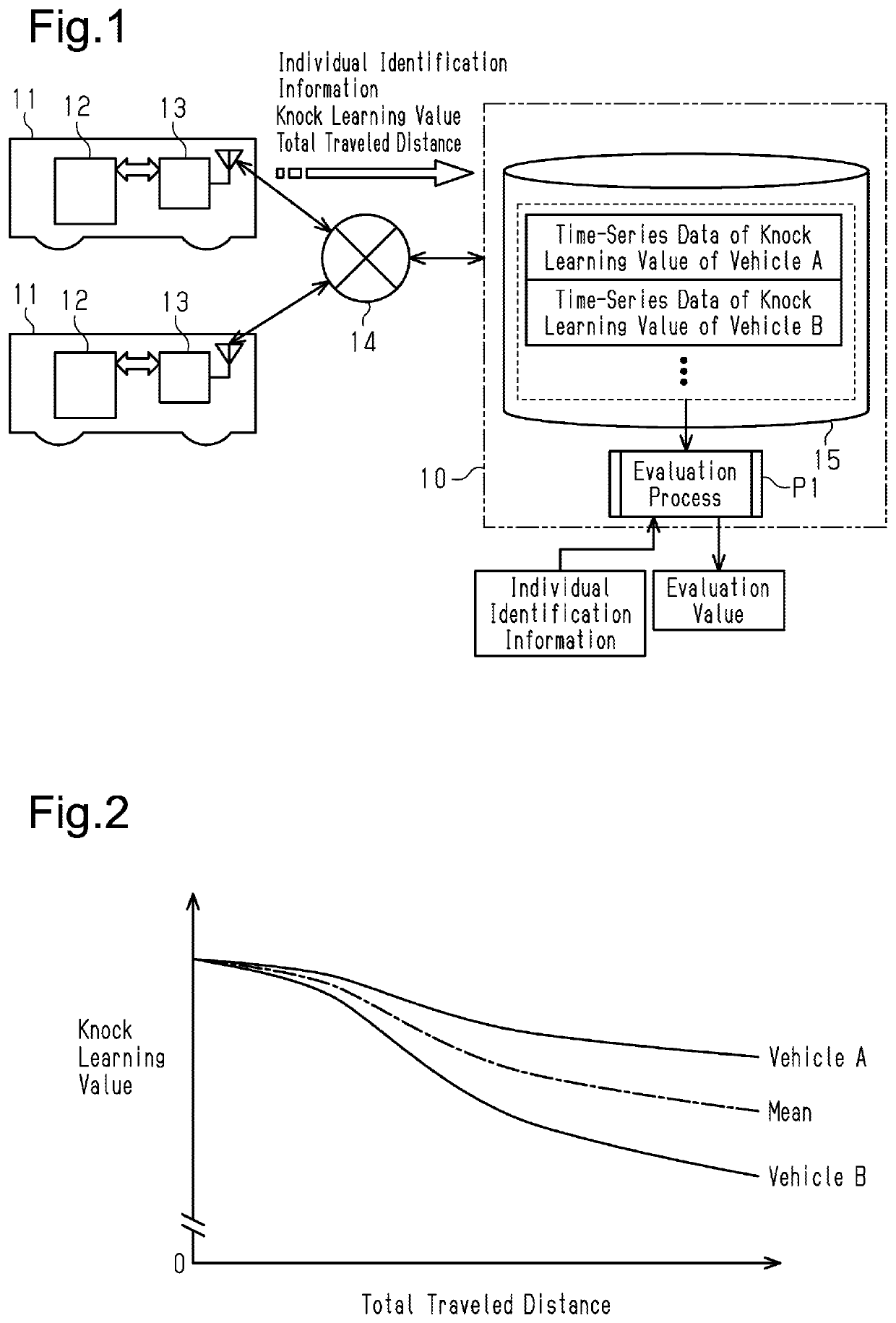
[0027]First, the configuration of the engine diagnostic system 10 according to the present embodiment will be described with reference to FIG. 1. The engine diagnostic system 10 is a computer system that manages a database 15. That is, the engine diagnostic system 10 is configured as a system that diagnoses the deterioration degree of an engine 12 mounted on each of vehicles 11 of the same model under management.

[0028]Each vehicle 11 under management of the engine diagnostic system 10 includes a control unit 13, which controls a variety of characteristics of the vehicle 11 including the engine 12. The control unit 13 includes a wireless transmission function and is capable of transmitting and receiving data to and from the engine diagnostic system 10 through a mobile communication network 14.

[0029]The cont...

second embodiment

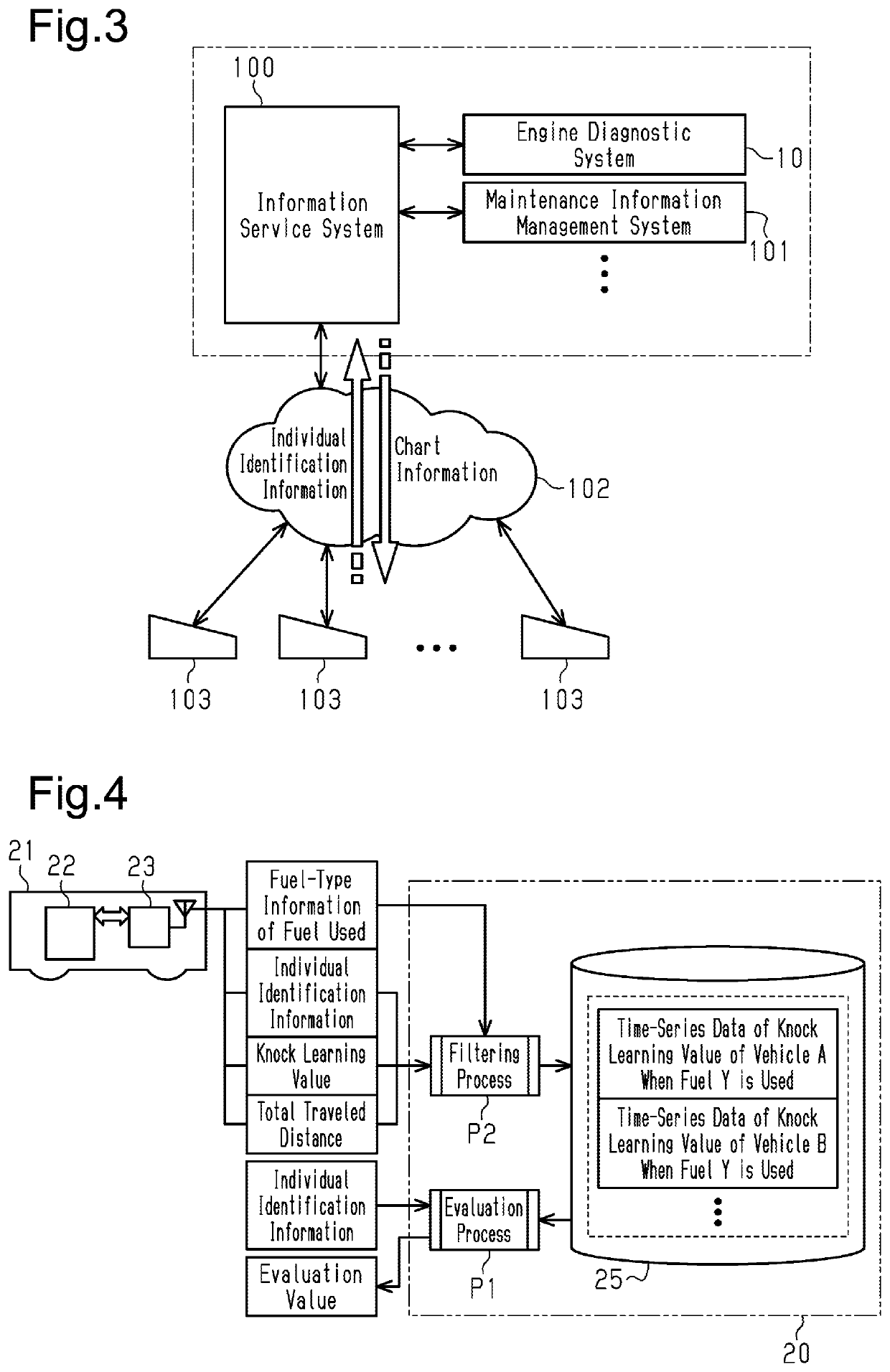
[0046]An engine diagnostic system 20 and an engine diagnosing method according to a second embodiment of the present disclosure will now be described in detail with reference to FIG. 4. In the present embodiment, like or the same reference numerals are given to those components that are like or the same as the corresponding components of the first embodiment, and the detailed description will be omitted.

[0047]Like the first embodiment, the engine diagnostic system 20 of the present embodiment shown in FIG. 4 is configured as a computer system that manages a database 25. Like the case in the first embodiment, the engine diagnostic system 20 of the present embodiment also executes the evaluation process P1, which computes the evaluation value indicating the deterioration degree of the engine using the time-series data of the knock learning value collected in the database 25.

[0048]An engine 22 of a vehicle 21 under management of the engine diagnostic system 20 of the present embodiment...

third embodiment

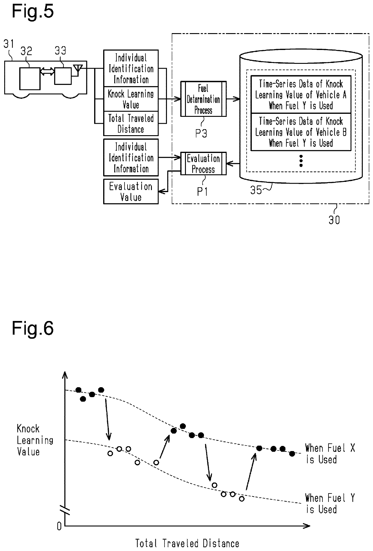
[0052]An engine diagnostic system 30 and an engine diagnosing method according to a third embodiment of the present disclosure will now be described in detail with reference to FIGS. 5 and 6. In the present embodiment, like or the same reference numerals are given to those components that are like or the same as the corresponding components of the above-described embodiments, and the detailed description will be omitted.

[0053]Like each of the above embodiments, the engine diagnostic system 30 of the present embodiment shown in FIG. 5 is configured as a computer system that manages a database 35. The engine diagnostic system 30 of the present embodiment also executes the evaluation process P1, which is the same as the cases in the above embodiments. That is, the evaluation process P1 computes the evaluation value indicating the deterioration degree of the engine using the time-series data of the knock learning value collected in the database 35.

[0054]Additionally, an engine 32 of a v...


PUM


Abstract

An engine diagnostic system is provided for diagnosing a deterioration degree of an engine mounted on a vehicle. The engine diagnostic system learns, as a knock learning value, a maximum advancement amount of an ignition timing that reduces knocking. A database stores time-series data of the knock learning value of the engine for each individual engine. The knock learning value is acquired from each of a plurality of vehicles of the same model. An evaluation process computes an evaluation value indicating the deterioration degree of a designated engine using the time-series data of the knock learning value of each engine stored in the database.

Description

BACKGROUND1. Field[0001]The present disclosure relates to an engine diagnostic system that diagnoses the deterioration degree of an engine mounted on a vehicle and to an engine diagnosing method that diagnoses the deterioration degree.2. Description of Related Art[0002]Knock control is known as a technique for controlling spark-ignition engines. In knock control, feedback control is performed on the basis of the output of a knock sensor to advance the ignition timing in the range that reduces the occurrence of knocking. As disclosed in Japanese Laid-Open Patent Publication No. 2004-28061, the maximum advancement amount of the ignition timing that reduces knocking is learned as a knock learning value in the knock control.[0003]The knock resistance of such an engine decreases in accordance with the deterioration of the engine over time.SUMMARY[0004]This Summary is provided to introduce a selection of concepts in a simplified form that are further described below in the Detailed Descri...

Claims


Application Information

Patent Timeline
Patent Type & Authority Patents(United States)
IPC IPC(8): F02D41/22F02D41/14F02P5/152F02D41/26F02D41/24
CPCF02D41/1498F02D41/22F02D41/2451F02D41/26F02P5/152F02D45/00F02D2200/0612F02P5/1527Y02T10/40
Inventor MIYAZAKI, TSUTOMU
Owner TOYOTA JIDOSHA KK
Why Eureka
Try Eureka