Method and a device for determining and displaying a flyaway distance for a rotorcraft while taking account of the height of waves

a technology of determining and displaying a flyaway distance and a rotorcraft, which is applied in the direction of using reradiation, navigation instruments, instruments, etc., can solve the problems of rotorcraft flying at very low altitude, putting a great strain on the engine of the rotorcraft, and rotorcraft may find itself in a dangerous situation

Active Publication Date: 2021-05-25
EUROCOPTER
View PDF17 Cites 0 Cited by
  • Summary
  • Abstract
  • Description
  • Claims
  • Application Information

AI Technical Summary

Benefits of technology

[0018]Under such circumstances, an object of the present invention is to enable the crew of a rotorcraft to know at all times, in the event of an engine failure, whether they have a necessary and sufficient flyaway distance relative to the free surface of water and in spite of the height fluctuations due to waves.
[0036]As a result, so long as the indicated current position of the rotorcraft is situated above this symbol for the flyaway distance HFlyA, the crew of the rotorcraft knows advantageously, e.g. on engaging an emergency operation, that a sufficient flyaway distance is available in the event of an engine failing. This flyaway distance is advantageously indicated to the pilot of the rotorcraft while taking account of variation in the height of the free water surface due to the presence of waves. This emergency operation can thus be undertaken in complete safety, even in the event of an engine failing. In contrast, if the current position of the rotorcraft is indicated as being below the symbol for the flyaway distance HFlyA, then the crew of the rotorcraft knows that sufficient flyaway distance is not available in the event of an engine failure, and that the altitude of the rotorcraft needs to be increased before it is safe to begin an emergency operation.
[0065]This fourth measurement for measuring the current relative height HCur may also be taken at a predefined distance from the rotorcraft, preferably ahead of the rotorcraft, with this predefined position relative to the rotorcraft then being situated at that predefined distance from the rotorcraft. The current position of the waves is then situated at this predefined distance from the rotorcraft. Such a fourth measurement ahead of the rotorcraft can be taken by way of example by using an ultrasound type device or indeed a LIDAR type device, and it serves advantageously to anticipate the arrival of the waves over which the rotorcraft is flying.
[0071]The term “long time constant” should be understood in comparison with the time between two waves, corresponding to the period of the waves. This wave period typically lies in the range 7 seconds (s) to 12 s, and the predefined decreasing curve of the filter needs to make use of a time constant that is several times greater than the wave period. For example, the time constant may lie in the range 120 s to several minutes. Specifically, an observation time of a few minutes makes it possible to obtain a good estimate of the maximum position of the waves, particularly since such an observation can begin well before the rotorcraft starts hovering, while it is approaching the zone of operation.

Problems solved by technology

Furthermore, rotorcraft often fly at very low altitude.
Such hovering or low speed flights are stages of flight that put a great strain on the engines of the rotorcraft.
Nevertheless, if an engine failure takes place during such an emergency operation, the rotorcraft may find itself in a situation that is dangerous, given its low altitude and its low speed of advance.
Under such circumstances, in the event of an engine failure taking place during hovering flight or flight at a low speed of advance, the rotorcraft needs to be accelerated quickly in order to reach some minimum airspeed, with this rapid acceleration giving rise to the rotorcraft losing altitude.
Nevertheless, the crew of a rotorcraft may not be in a position to re-estimate accurately the value of this flyaway height during flight at low speeds of advance or in the proximity of hovering flight.
Furthermore, during a rescue operation at sea, variation in the height of the free surface of the water as a result of waves can make readings of the radioaltimeter height scale on a display instrument on board the rotorcraft misleading.

Method used


Image

  • Method and a device for determining and displaying a flyaway distance for a rotorcraft while taking account of the height of waves
  • Method and a device for determining and displaying a flyaway distance for a rotorcraft while taking account of the height of waves

Examples


Embodiment Construction

[0100]Elements present in more than one of the figures are given the same references in each of them.

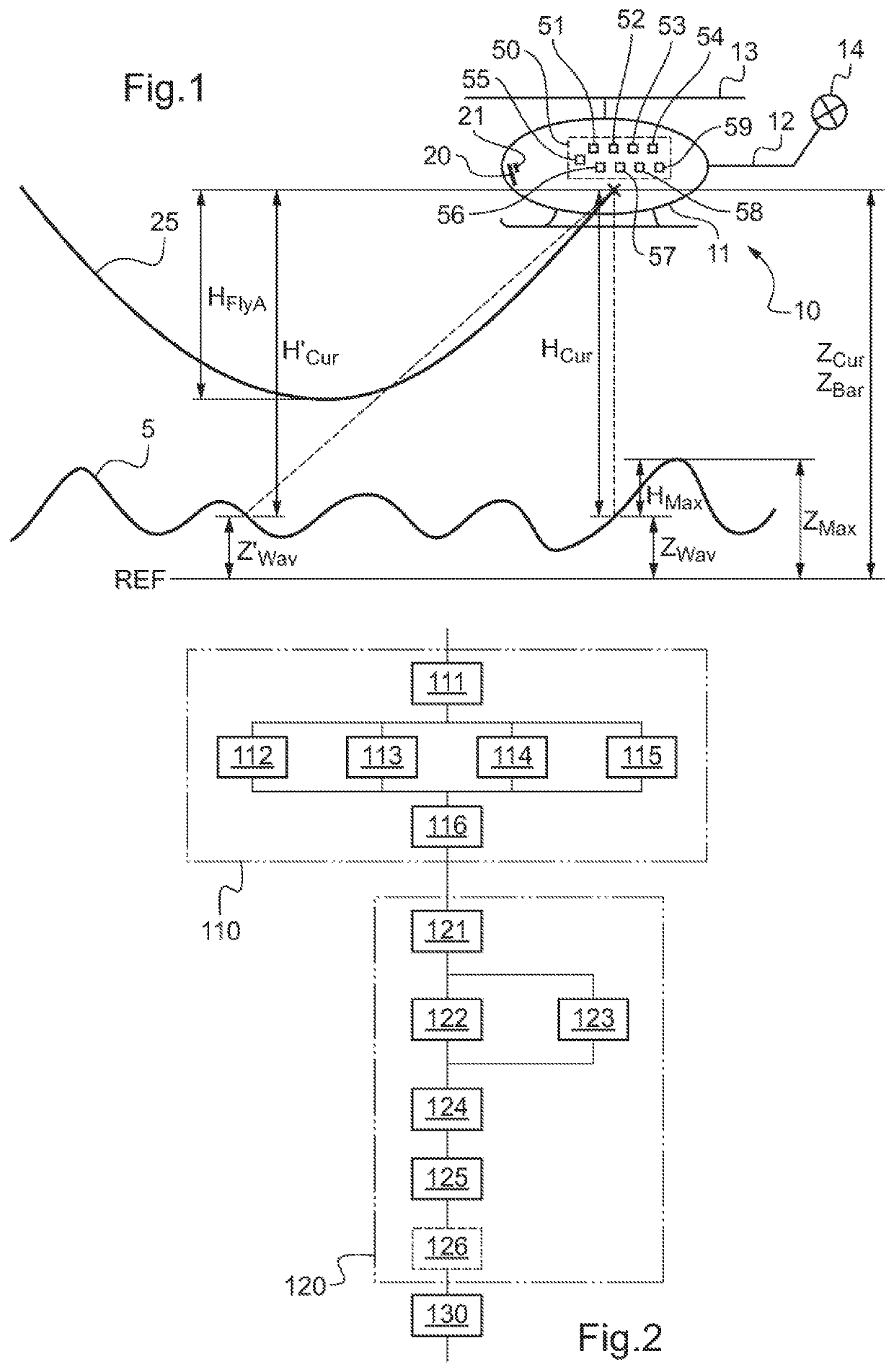
[0101]FIG. 1 shows a rotorcraft 10, also referred to as a “rotary wing aircraft” flying over a free water surface 5. The rotorcraft 10 comprises in particular a fuselage 11, a tail boom 12, a main rotor 13 providing it with lift and possibly also propulsion, and a tail rotor 14 positioned at the rear end of the tail boom 12. The rotorcraft 10 also has two engines that are not shown. The rotorcraft 10 is for use in particular in performing search and rescue missions at sea. During such operations, the rotorcraft 10 needs to act in complete safety while hovering or while flying at low speeds and at very low altitude in an environment that is often disturbed, and in particular with a free water surface that is rough, possibly associated with poor visibility.

[0102]The rotorcraft 10 also has a device 50 for determining and displaying a flyaway distance HFlyA of a rotorcraft while taking a...


PUM


Abstract

A method and a device for determining and displaying a flyaway distance for a rotorcraft in the event of an engine of the rotorcraft failing, and while taking account of the height of waves being overflown by the rotorcraft. The method includes a first determination for determining a flyaway distance of the rotorcraft in the event of a failure of an engine and under current flying conditions, a second determination for determining a maximum altitude of the waves being overflown by the rotorcraft and displaying the flyaway distance and the maximum altitude on a display instrument of the rotorcraft indicating the relative height of the rotorcraft or else its altitude. A safety margin is preferably added to the maximum altitude of the waves, or else to the flyaway distance of the rotorcraft.

Description

CROSS-REFERENCE TO RELATED APPLICATIONS[0001]This application claims priority to French patent application No. FR 1800508 filed on May 24, 2018, the disclosure of which is incorporated in its entirety by reference herein.BACKGROUND OF THE INVENTION(1) Field of the Invention[0002]The present invention relates to the general technical field of providing assistance in the piloting of aircraft, and in particular assistance in the piloting of a rotorcraft having a plurality of engines and in the event of one of the engines failing.[0003]The present invention relates to a method of determining and displaying a flyaway distance for a rotorcraft relative to a free water surface while taking account of the height of waves, and also to a device that performs the method.(2) Description of Related Art[0004]A rotorcraft, also known as a “rotary wing aircraft”, is a flying machine that differs from other powered aircraft mainly by its ability both to fly in cruising flight at high speeds and also...

Claims


Application Information

Patent Timeline
Patent Type & Authority Patents(United States)
IPC IPC(8): G01C13/00G05D1/04G05D1/10G06F17/11B64C27/12G01S13/935G01S17/933
CPCG01C13/004G05D1/042G05D1/105G06F17/11B64C27/12G01C23/00G01S17/933G08G5/0056B64D45/04G01S17/58G01S13/60G01S13/935G01S13/882
Inventor SALESSE-LAVERGNE, MARC
Owner EUROCOPTER
Why Eureka
Try Eureka