Method and device for sludge handling

a technology for thawing sludge and sludge, which is applied in the direction of filtration separation, separation processes, radioactive contaminants, etc., can solve the problems of bringing a lot of water into the tank in which the sludge is sucked, limiting the handling of sludge, and reducing the water content of thawed sludge. , to achieve the effect of reducing the water content of thawed s

Inactive Publication Date: 2013-08-08
STUDSVIK AB
View PDF6 Cites 0 Cited by
  • Summary
  • Abstract
  • Description
  • Claims
  • Application Information

AI Technical Summary

Benefits of technology

[0020]In order to further decrease the water content in the thawed sludge water may be removed during thawing of the sludge in order to maintain an essentially dry environment in the container.
[0021]It is also possible to let dry air circulate through the container during thawing of the sludge. To decrease the water content of the thawed sludge further.

Problems solved by technology

This put numerous restrictions on the handling of the sludge.
A drawback with using the described method is that the sucking of sludge from the bottom stirs up the sludge.
Another drawback is that the suction of sludge from the bottom also will bring a lot of water into the tank into which the sludge is sucked.
The method described is, however, complicated and requires a lot of equipment.
Furthermore, the problem of stirring up sludge from the bottom of the tank during suction of sludge from the bottom still remains.

Method used


Image

  • Method and device for sludge handling
  • Method and device for sludge handling
  • Method and device for sludge handling

Examples


Embodiment Construction

[0034]In the following description of preferred embodiments similar features in the different figures will be denoted with the same reference numeral. The drawings are only schematic and not drawn to scale.

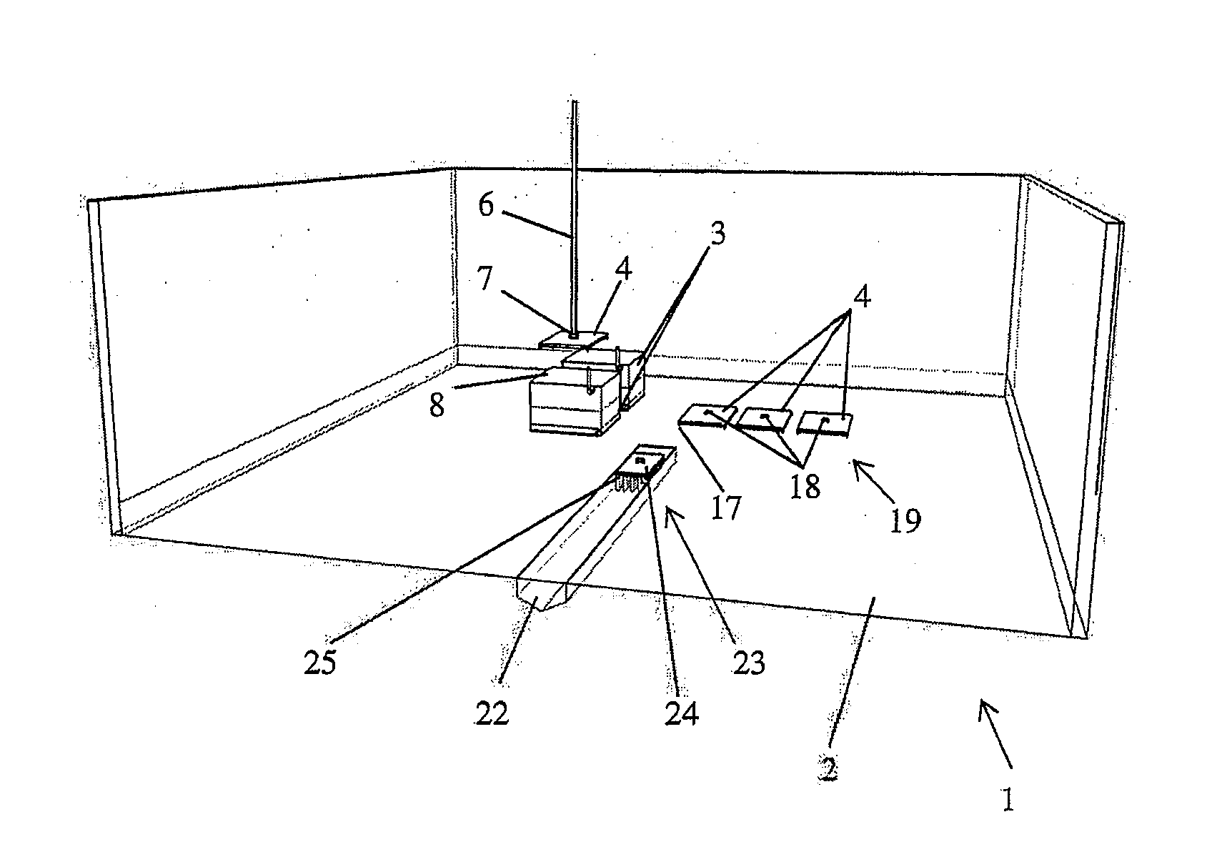
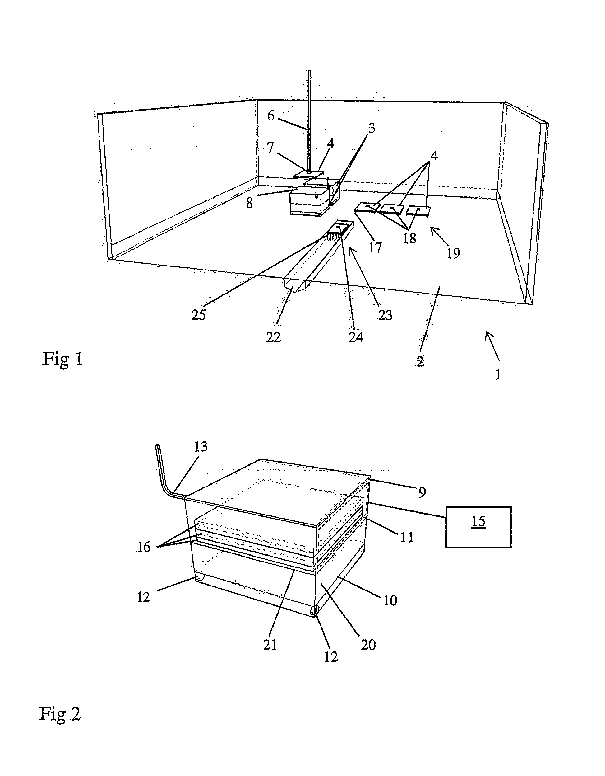
[0035]FIG. 1 is a schematic view of a basin 1 on the bottom 2 of which an apparatus according to the present invention for handling sludge are arranged. The apparatuses comprise two containers 3 arranged on the bottom of the basin and arranged with means for receiving frozen sludge. The apparatus also comprise four movable freezing devices 4 for freezing sludge, which device has a coolable essentially flat surface. The coolable surface 19 of the freezing device is a coolable / heatable surface that is also arranged to be heatable. Such coolable / heatable surfaces are well known in the art and will not be described in detail herein.

[0036]Three of the freezing devices 4 are arranged on the bottom 2 of the basin arranged to freeze the sludge beneath the freezing devices. The freezing de...


PUM

PropertyMeasurementUnit
distanceaaaaaaaaaa
temperatureaaaaaaaaaa
freezingaaaaaaaaaa

Abstract

A method for handling sludge arranged on the bottom (2) of a water filled basin (1), wherein the water defining a surface, is described. The method comprises the steps of freezing the sludge in a portion of the bottom (2) of the basin (1), arranging a closable container (3) in the basin (1) below the surface of the water, which container (3) comprises a collecting filter, moving the frozen sludge into the container (3) to a position above the collecting filter, closing the container (3), and thawing the frozen sludge in the container (3). An apparatus for performing the method is also described.

Description

TECHNICAL FIELD [0001]The present invention relates to a method and a device for sludge handling. More specifically the present invention relates to a method and a device for handling of radioactive sludge which has sedimentated on a surface. In particular the invention relates to such sludge that has sedimentated on the bottom of a basin for storage of nuclear fuel.DESCRIPTION OF THE PRIOR ART[0002]Nuclear power plants use nuclear fuel to produce electric energy. The nuclear fuel is usually in the form of fuel pellets that are enclosed by fuel claddings to form fuel rods. A number of fuel rods are arranged in a fuel element. A number of fuel elements form a reactor core. The reactor core is arranged in a reactor tank. In most reactors the reactor tank is filled with water that encloses the reactor core and which water is to be heated by the reactor core to form steam. The steam drives turbines that in turn drive generators. The nuclear fuel has to be replaced regularly. The used fu...

Claims


Application Information

Patent Timeline
Patent Type & Authority Applications(United States)
IPC IPC(8): C02F11/20
CPCB01D21/245C02F11/20C02F2101/006B01D21/009G21F9/20G21F9/30G21F9/304G21F9/06
Inventor ROSTMARK, MATS-JOHANMAKSIMAINEN, ERIKROSTMARK, SUSANNE
Owner STUDSVIK AB
Why Eureka
Try Eureka