Supercharge Your Innovation With Domain-Expert AI Agents!

Circuit testing system and method of operation

a circuit and testing system technology, applied in the direction of indicating current/voltage, coupling device connection, instruments, etc., can solve the problems of difficult to determine which circuit breaker controls any particular circuit, time-consuming and laborious task, and not often identified circuits by nam

Active Publication Date: 2021-05-25
STONEBRAKER STEPHEN E
View PDF7 Cites 0 Cited by
  • Summary
  • Abstract
  • Description
  • Claims
  • Application Information

AI Technical Summary

Benefits of technology

[0006]The present inventor has recognized that it would be advantageous to provide a circuit testing system operable by a single user and which would allow a user to identify a circuit breaker associated with a particular electrical circuit. The present inventor has further recognized that it would be advantageous to allow the user to test an electrical circuit and identify a circuit breaker associated with a remote electrical circuit from an area located proximate the electrical panel in which the circuit breaker is housed.

Problems solved by technology

The problem is that circuits are not often identified by name at the electrical panel.
It can therefore be quite difficult to determine which circuit breaker controls any particular circuit.
Having to repeatedly move from the electrical panel to a remote room to check whether or not a particular circuit is energized or non-energized (e.g. checking to see whether the light is on or off) is a time consuming and laborious task as the electrical panel is usually located far away from where the circuit is providing power.
Although this may save time, another person may not always be available and utilizing another person may be more expensive than performing the task with one person.

Method used


Image

  • Circuit testing system and method of operation
  • Circuit testing system and method of operation
  • Circuit testing system and method of operation

Examples


Embodiment Construction

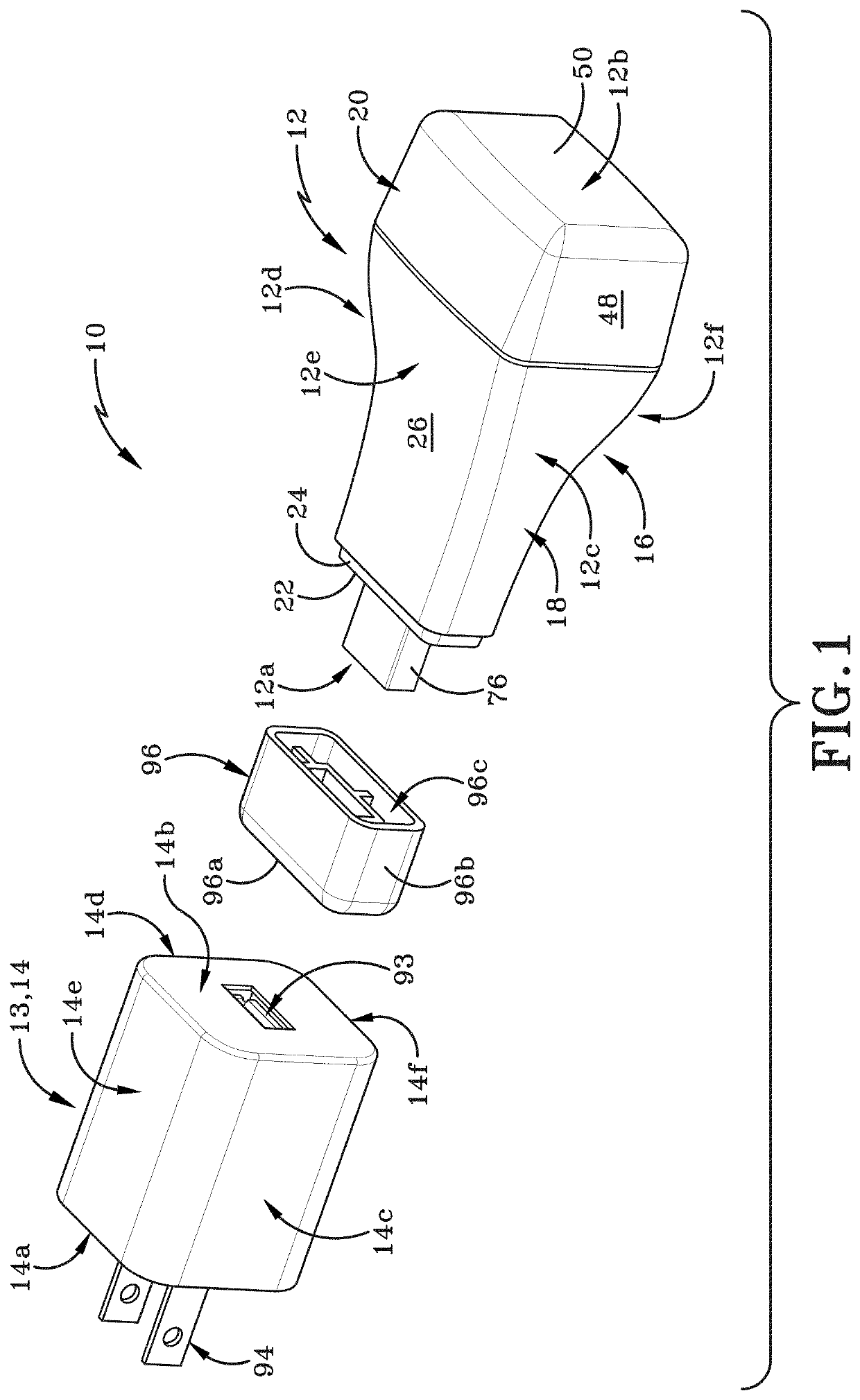
[0027]Referring to FIGS. 1-8, there is shown a circuit testing system for identifying a circuit breaker associated with an electrical circuit in accordance with one aspect of the present disclosure, with the circuit testing system generally indicated at 10.

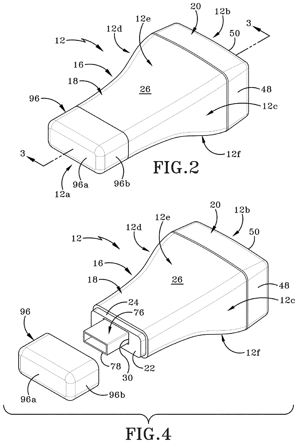
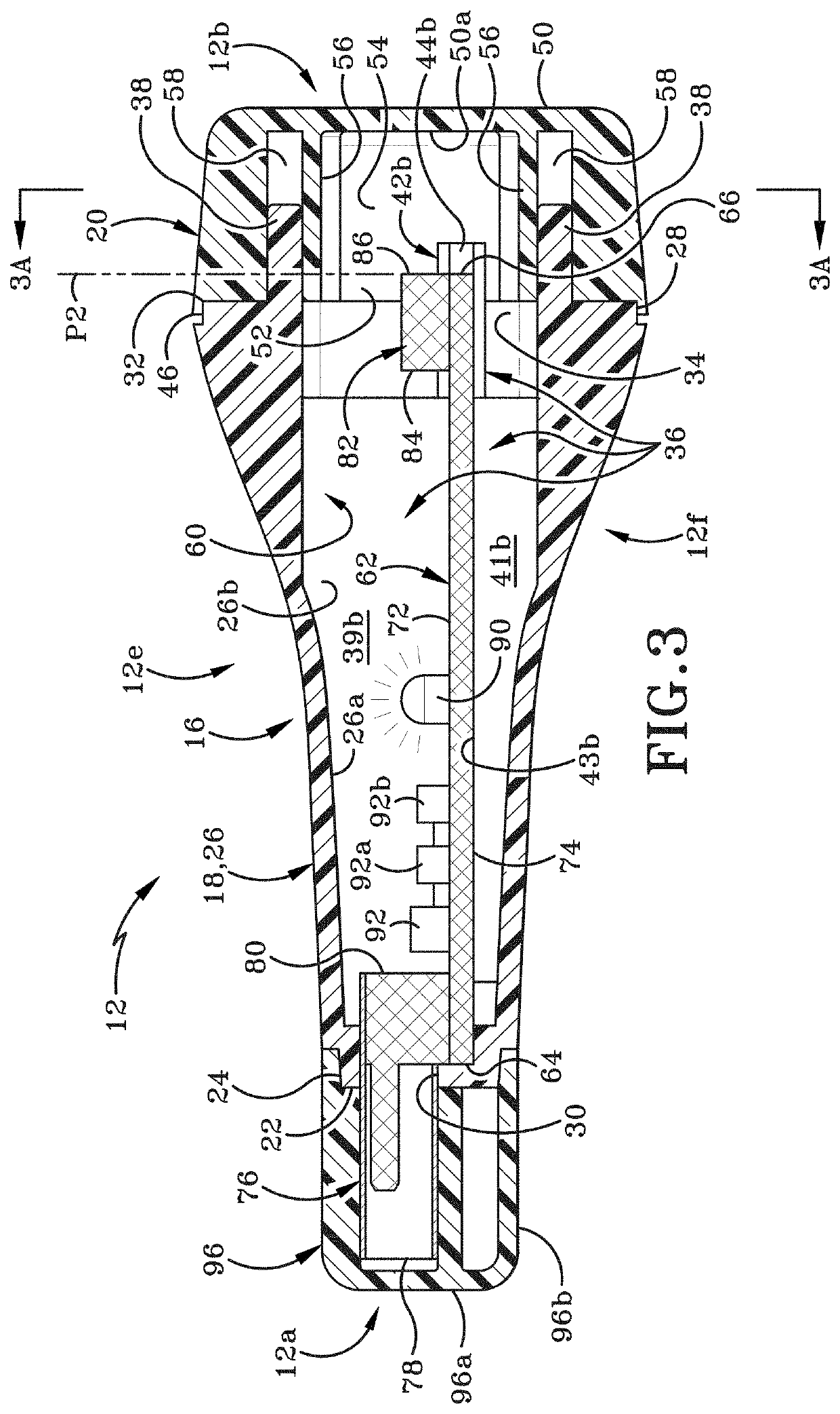
[0028]With primary reference to FIG. 1 and FIG. 3, circuit testing system 10 includes a circuit testing module 12, which may also be referred to herein as a module, and a connector mechanism 13. Module 12 includes a first end 12a, a second end 12b, a first side 12c, a second side 12d, a top 12e, and a bottom 12f. First end 12a and second end 12b define a longitudinal direction therebetween. First side 12c and second side 12d define a transverse direction therebetween. Top 12e and bottom 12f define a vertical direction therebetween.

[0029]With reference to FIG. 1 through FIG. 5, module 12 includes a housing 16 having a first section 18 and a second section 20. First section 18 includes a front wall 22, a front ledge 24, a central wa...


PUM


Abstract

A circuit testing system for identifying a circuit breaker associated with an electrical circuit is disclosed. The circuit testing system includes a circuit testing module and a connector mechanism provided on the circuit testing module. The connector mechanism is adapted to operably engage the circuit testing module with an electrical connection point of the electrical circuit. The circuit testing system further includes a remote electronic device wirelessly connected to circuit testing module. The connector mechanism is one of one or more prongs, a socket, and a probe; and the one of the one or more prongs, the socket, and the probe operably engages the circuit testing module to the electrical connection point.

Description

BACKGROUNDTechnical Field[0001]This disclosure is generally directed to electrical testing devices. More particularly, this disclosure relates to electrical testing devices utilized to determine whether electrical circuits are energized or non-energized. Specifically, this disclosure is directed to a wireless circuit testing system and a method for testing energized and non-energized electrical circuits to identify which circuit breakers control particular electrical circuits.Background Information[0002]An electrical panel is a component of an electricity supply system that divides an electrical power feed into subsidiary circuits. The electrical panel is a common enclosure that houses a protective circuit breaker for each circuit in the electrical system. The electricity in each circuit typically flows from a circuit breaker to an electrical connection point, such as a standard electrical outlet or light receptacle, and then flows back to the electrical panel. Since the electricity...

Claims


Application Information

Patent Timeline
Patent Type & Authority Patents(United States)
IPC IPC(8): H01H83/04H01H71/10H01R27/02H01R24/60H01R24/28
CPCH01H83/04H01H71/10H01R24/28H01R24/60H01R27/02G01R19/145G01R31/3277H01R31/06H01R2201/20
Inventor STONEBRAKER, STEPHEN E.
Owner STONEBRAKER STEPHEN E
Features
  • R&D
  • Intellectual Property
  • Life Sciences
  • Materials
  • Tech Scout
  • Unparalleled Data Quality
  • Higher Quality Content
  • 60% Fewer Hallucinations
Learn More