Supercharge Your Innovation With Domain-Expert AI Agents!

Side rail and manufacturing method for side rail

a manufacturing method and side rail technology, applied in the direction of manufacturing tools, superstructure connections, transportation and packaging, etc., can solve the problems of large increase in vehicle body weight, and disadvantages in practical use, so as to increase the weight of the vehicle body, increase the cost of manufacturing, and increase the anti-rust effect of the anti-rust coating

Active Publication Date: 2021-06-01
TOYOTA JIDOSHA KK
View PDF23 Cites 0 Cited by
  • Summary
  • Abstract
  • Description
  • Claims
  • Application Information

AI Technical Summary

Benefits of technology

The patent provides a side rail that improves the smoothness of a vehicle's ride without adding extra weight or cost to the vehicle body. The reinforcement region of the side rail has joined portions where base members and reinforcement plate members are joined together. This design helps to reduce the amount of movement and vibration during driving.

Problems solved by technology

Unfortunately, in order to enlarge the sectional shape of the side rail, it is required to secure a large space for arranging the side rail, which is disadvantageous in practical use.
Such solutions that increase the plate thickness of the entire steel plate configuring the side rail, and that lay and weld the reinforcements onto the inner surfaces of the side rail might cause a great increase in weight of the vehicle body, which is not preferable.
In addition, such a solution that improves the cab mount structure might cause a great increase in weight of the vehicle body or a great increase in cost for manufacturing the vehicle body, which is not preferable.
If the base members are joined to the reinforcement plate members by arc welding, welding spatters adhere on the vicinities of the welded portions, and oxided scales are present thereon due to thermal influence; consequently, it becomes difficult to apply a coating material when antirust coating is carried out, and thus it becomes difficult to obtain a high antirust effect.

Method used


Image

  • Side rail and manufacturing method for side rail
  • Side rail and manufacturing method for side rail
  • Side rail and manufacturing method for side rail

Examples


Embodiment Construction

[0034]Hereinafter, an embodiment of the present disclosure will be described with reference to the drawings. In the present embodiment, description will be provided on the case in which the present disclosure is applied to a side rail of a vehicle body frame configured as a rudder frame applied to a pickup truck or the like.

[0035]Outline of Structure of Vehicle Body Frame

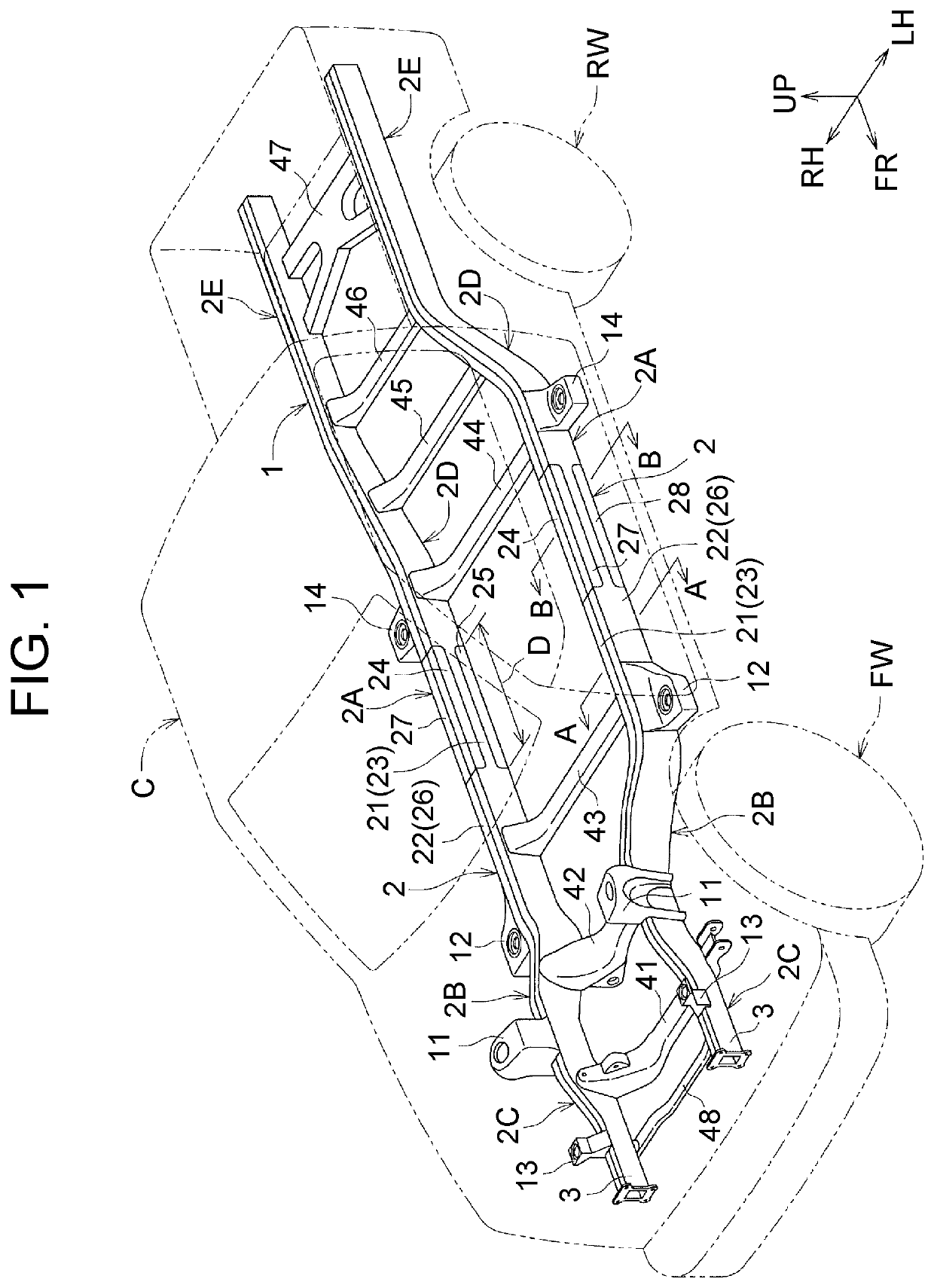
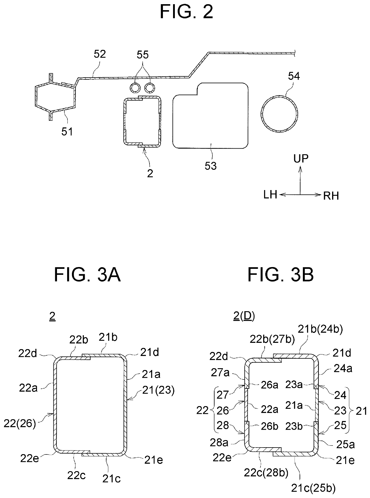
[0036]FIG. 1 is a perspective view showing a vehicle body frame 1 according to the present embodiment. In FIG. 1, the vehicle body frame 1 is indicated by solid lines, a cabin C and wheels FW, RW are indicated by imaginary lines. FIG. 2 is a sectional view of the vehicle at a position corresponding to line B-B in FIG. 1. In each drawing, an arrow FR indicates a frontward direction, an arrow UP indicates an upward direction, an arrow RH indicates a rightward direction, and an arrow LH indicates a leftward direction, respectively.

[0037]As shown in FIG. 1, the vehicle body frame 1 includes a pair of right and left side...


PUM

PropertyMeasurementUnit
tensile strengthaaaaaaaaaa
thicknessaaaaaaaaaa
thicknessaaaaaaaaaa

Abstract

A side rail includes a reinforcement region having a closed-section structure by base members and reinforcement plate members having a greater plate thickness than a plate thickness of the base members. In the reinforcement region, in a state in which the reinforcement plate members are fitted in fitting portions provided at positions corresponding to respective corner portions in the base members, the base members and the reinforcement plate members are joined to each other by laser welding.

Description

INCORPORATION BY REFERENCE[0001]The disclosure of Japanese Patent Application No. 2017-200342 filed on Oct. 16, 2017 including the specification, drawings and abstract is incorporated herein by reference in its entirety.BACKGROUND1. Technical Field[0002]The present disclosure relates to a side rail extending along the longitudinal direction of a vehicle body and formed in a closed-section structure in a polygonal shape, and relates to a manufacturing method for this side rail.2. Description of Related Art[0003]Conventionally, for example, as disclosed in Japanese Patent Application Publication No. 2005-132200 and Japanese Patent Application Publication No. 2009-12626, a vehicle body frame of a truck, a bus, or the like includes a pair of right and left side rails (also referred to as side frames) extending in the longitudinal direction of a vehicle body, and cross members suspended between these side rails.[0004]In the vehicle body frame of this type, it is desired to provide a solu...

Claims


Application Information

Patent Timeline
Patent Type & Authority Patents(United States)
IPC IPC(8): B62D21/15B62D27/02B62D21/02B23K26/00B23K26/24B62D21/03
CPCB62D27/023B23K26/0093B23K26/24B62D21/02B62D21/15B62D21/03B23K26/21
Inventor KITAMURA, YOSHIAKIYAMANE, GOUTA
Owner TOYOTA JIDOSHA KK
Features
  • R&D
  • Intellectual Property
  • Life Sciences
  • Materials
  • Tech Scout
  • Unparalleled Data Quality
  • Higher Quality Content
  • 60% Fewer Hallucinations
Learn More