
Directive multiway loudspeaker with a waveguide

a waveguide and direct-multi-way technology, applied in the field of loudspeakers, can solve the problems of deteriorating the quality of the audio signal audible to the listener, affecting the dynamic performance of the driver, and affecting the sound quality of the audio signal, so as to achieve the effect of small volume of the loudspeaker

Active Publication Date: 2021-06-01
GENELEC
View PDF12 Cites 3 Cited by
  • Summary
  • Abstract
  • Description
  • Claims
  • Application Information

AI Technical Summary

Benefits of technology

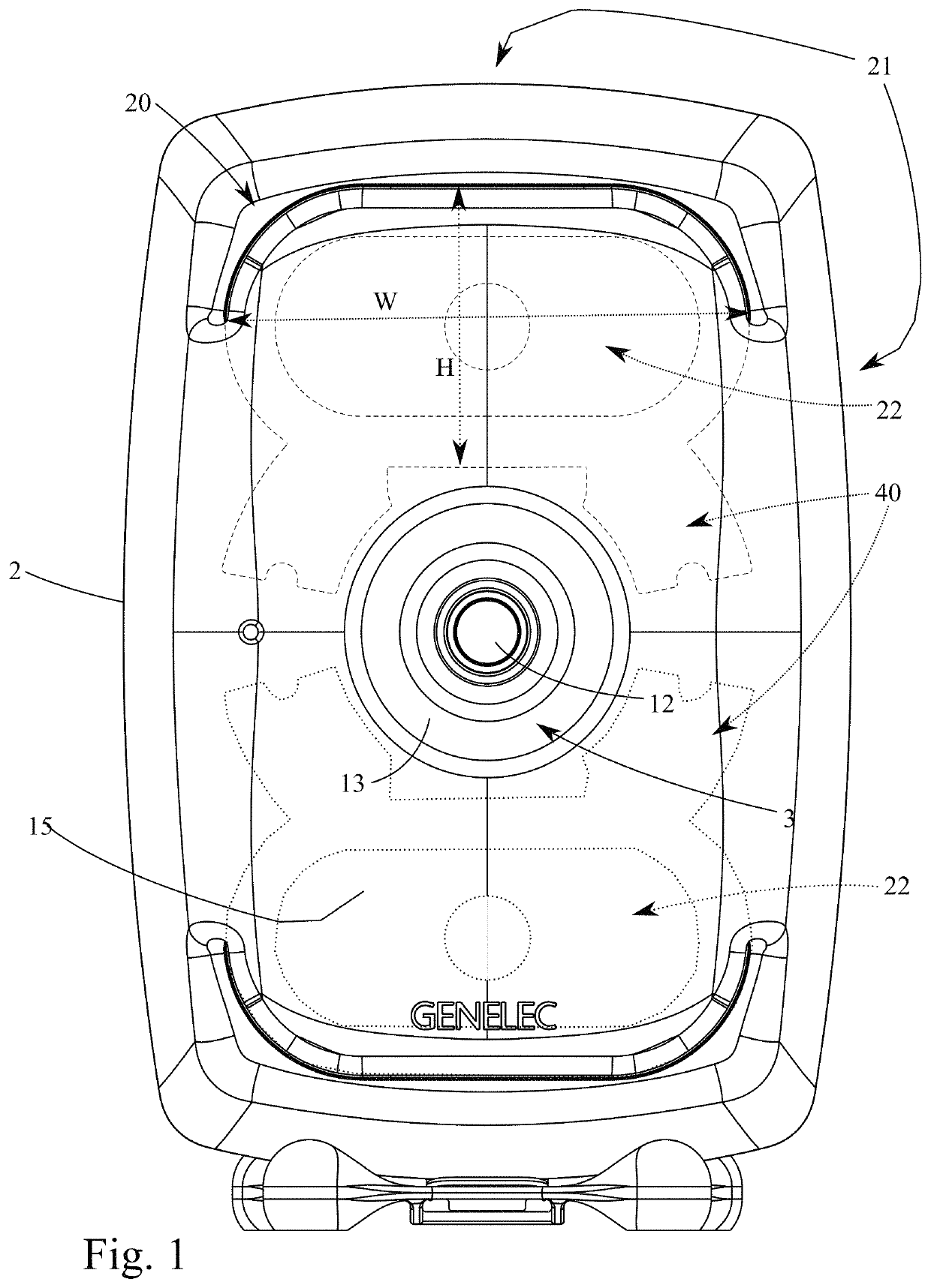
The present invention provides a loudspeaker with advantages such as suppressed resonances, improved sound quality, and a continuous waveguide for mid- and high frequencies. The invention also optimizes sound pressure distribution and reduces wall reflections, resulting in a more natural sound for the human ear. The overall volume of the loudspeaker is kept small while the whole audio range is directed precisely to one "sweet spot".

Problems solved by technology

In the prior art especially loudspeakers with two or more drivers (multiway loudspeakers) have exhibited problems with sound diffractions created by discontinuities on the front baffle surface (Face) of the loudspeaker.
When a smaller size loudspeaker is designed, all the drivers usually cannot be placed in the center of the waveguide (such as the low frequency radiator, the woofer) the surface area taken by these other drivers and the drivers themselves will either limit the baffle area available for the waveguide or additionally create harmful diffractions of audio energy, causing deterioration of the quality of the audio signal audible to the listener.
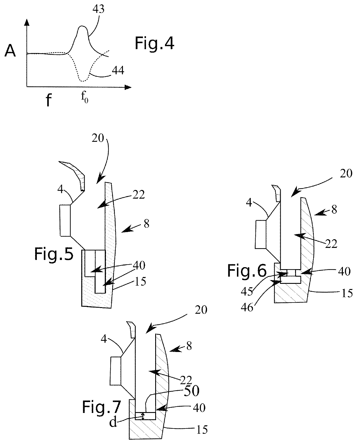
Covering the low frequency driver may cause some problems with the dynamic performance of the driver because the volume displacement of air by the driver requires sufficient openings to allow flow of air.
In addition the sub volume in front of the woofer may cause unwanted resonances.

Method used


Image

  • Directive multiway loudspeaker with a waveguide
  • Directive multiway loudspeaker with a waveguide
  • Directive multiway loudspeaker with a waveguide

Examples


Embodiment Construction

List of Used Terms

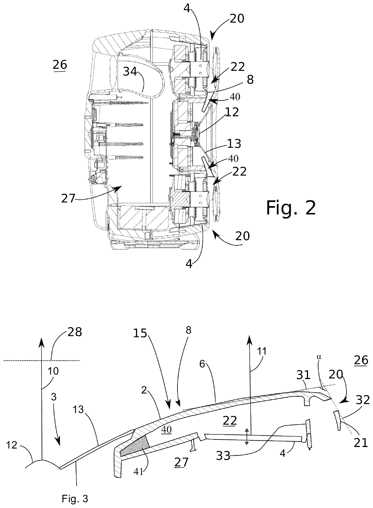
[0031]1 loudspeaker[0032]2 enclosure[0033]3 waveguide driver, also coaxial drive or tweeter only[0034]4 woofer, low frequency driver, additional driver[0035]5 front port (opening) for the woofer, low frequency driver having an outer rim on the surface of the enclosure 2 the rim defining a plane of the rim of the front port[0036]6 acoustically selectively transparent layer[0037]7 support structure for the acoustically transparent layer[0038]8 three dimensional waveguide surface, also a front surface (Face) of the enclosure 2 radiating the main acoustic power having a smooth continuous surface with axially symmetrical features around the centre of the waveguide driver 3[0039]9 sweet spot for multiple loudspeakers[0040]10 first acoustic axis[0041]11 second acoustic axis[0042]12 tweeter[0043]13 midrange driver[0044]15 front portion (wall) of the enclosure, (may also be a waveguide surface 8), a frontal baffle portion, the front portion radiating the main acoustic power...


PUM


Abstract

The present invention relates to a loudspeaker including an enclosure having front portion, side portions and back portion defining an inner volume, the front portion is formed as a waveguide surface and includes at least one driver in the center of the waveguide surface and is capable to radiate the main acoustic power of the loudspeaker to ambient volume in direction of first acoustic axis, and an additional driver attached to the enclosure. In accordance with the invention the additional driver is attached inside the enclosure such that a sub volume is formed inside the inner volume, the sub volume limited by the driver, spacers between the driver and the front portion, and the front portion of the enclosure, and at least one port is adapted to open from the sub volume to ambient volume either to side portion or back portion of the enclosure and at least one resonator acoustically connected to the sub volume, the resonator being tuned to at least one of unwanted resonances of the sub volume.

Description

FIELD OF THE INVENTION[0001]The present invention relates to loudspeakers. In particular, the present invention relates to loudspeakers equipped with a waveguide.[0002]To be exact, the present invention relates to the preamble portion of claim 1.PRIOR ART[0003]In the prior art especially loudspeakers with two or more drivers (multiway loudspeakers) have exhibited problems with sound diffractions created by discontinuities on the front baffle surface (Face) of the loudspeaker. In practice the high frequency driver (tweeter) has been the most critical part in this sense. The applicant of the present application has created solutions where the surroundings of the tweeter have been formed as a continuous waveguide for high and midrange frequency audio signals either merely for a tweeter and / or midrange driver or alternatively for a coaxial midrange-tweeter driver.[0004]In this application, these kinds of sound sources are referred to as waveguide drivers and they include any drivers loc...

Claims


Application Information

Patent Timeline
Patent Type & Authority Patents(United States)
IPC IPC(8): H04R25/00H04R1/28H04R1/02H04R1/22H04R1/24H04R1/26
CPCH04R1/2842H04R1/023H04R1/227H04R1/24H04R1/26H04R1/2849H04R1/2873H04R1/2888H04R1/345
Inventor MÄKIVIRTA, AKIHOLM, JUHAVÄISÄNEN, JUSSINAGHIAN, SIAMÄKMARTIKAINEN, ILPO
Owner GENELEC
Learn More