Golf club head with improved variable thickness striking face

a golf club and variable thickness technology, applied in the field of golf clubs, can solve the problems of exceeding the limits set by the governing bodies, difficult to implement the test with portable equipment, and difficulty in achieving the effect of constant thickness, variable thickness, and constant thickness

Active Publication Date: 2021-06-15
ACUSHNET CO
View PDF20 Cites 3 Cited by
  • Summary
  • Abstract
  • Description
  • Claims
  • Application Information

AI Technical Summary

Benefits of technology

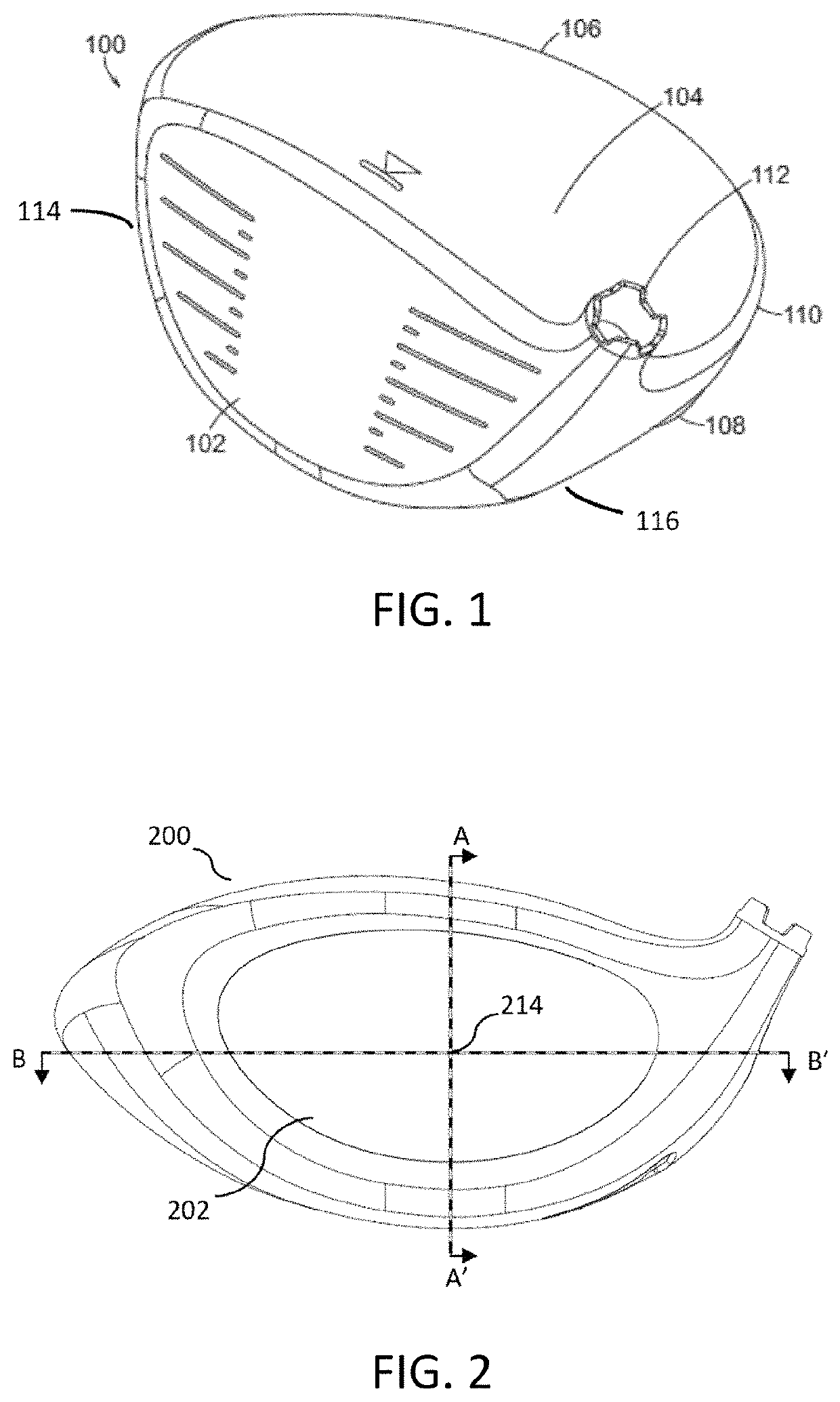
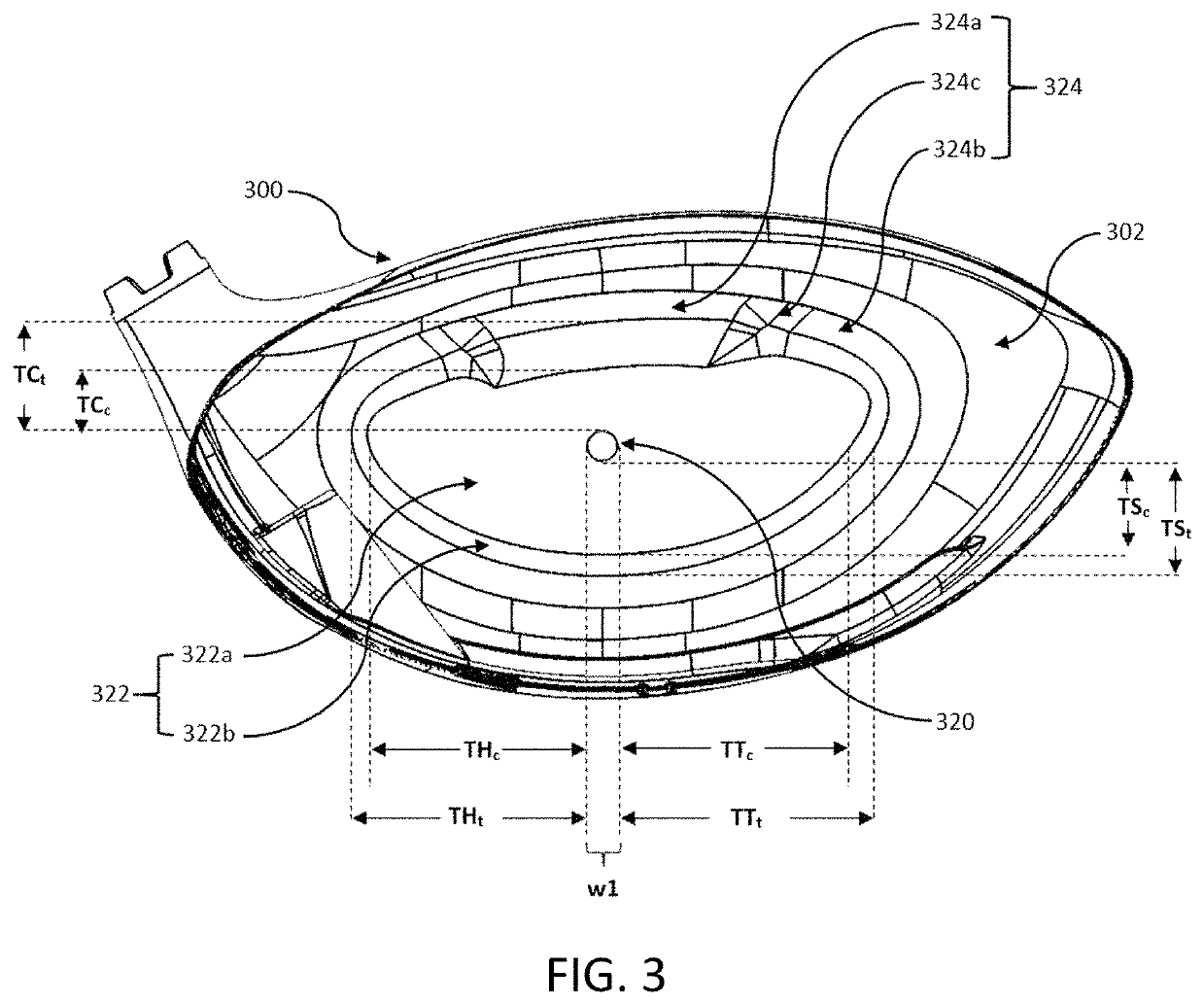
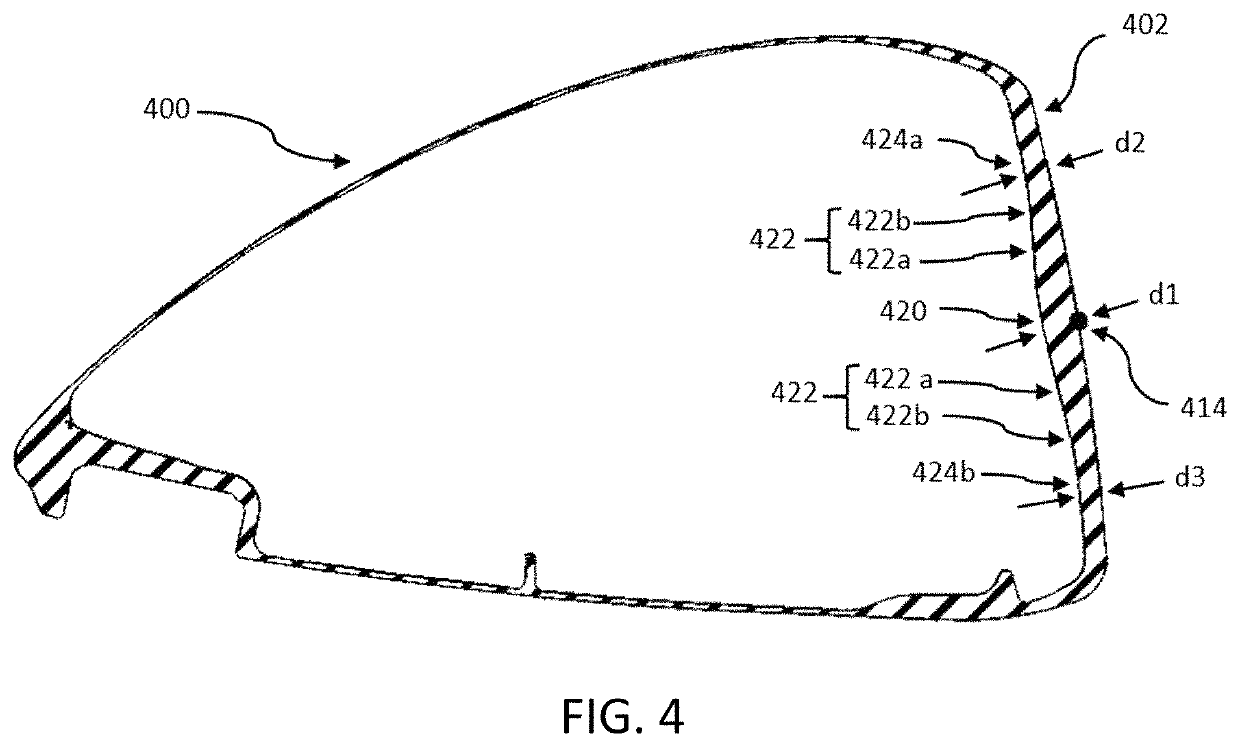
[0025]According to an aspect of the present invention, a golf club head is provided that includes a crown, a sole, and a skirt. The golf club head may further include a striking face portion located at a frontal portion of said golf club head adapted to strike a golf ball, said striking face may include a central region having a substantially constant thickness; a transition region surrounding said central region and having a variable thickness between that of said central region and a perimeter region; and said perimeter region surrounding said transition region. The perimeter region may include a first perimeter sub-region having a substantially constant thickness that is less than said thickness of said central region; a second perimeter sub-region having a substantially constant thickness that is less than said thickness of said first perimeter sub-region; and transition perimeter sub-regions having a thickness that decreases between said thickness of said first perimeter sub-region and said thickness of said second perimeter sub-region.

Problems solved by technology

Specifically, among other limitations, the governing bodies have set limits on the coefficient of restitution (COR) of the face of the golf club.
While COR is a useful metric for analyzing golf club heads, it is difficult to implement the test with portable equipment.
Such CT hotspots occurring away from the center of the striking face may result in CT values that exceed the limits set by the governing bodies without offering a performance benefit.
However, when the highest CT values on the striking face are located away from the center of the striking face, the center of the striking face will exhibit lower CT values and therefore lower ball speeds.
Hence, as it can be seen from above, despite all the advancement in golf club technology, the current art has not carefully examined the geometry of the variable face thickness profile behind the striking face as it relates to ensuring not only a high COR, but also a more uniform CT across the striking face.

Method used


Image

  • Golf club head with improved variable thickness striking face
  • Golf club head with improved variable thickness striking face
  • Golf club head with improved variable thickness striking face

Examples


Embodiment Construction

[0044]In the following detailed description, reference is made to the accompanying drawings, which form a part of the present disclosure. The illustrative embodiments described in the detailed description, drawings, and claims are not meant to be limiting. Other embodiments may be utilized, and other changes may be made, without departing from the spirit or scope of the subject matter presented herein. It will be readily understood that the aspects of the present disclosure, as generally described herein, and illustrated in the Figures, can be arranged, substituted, combined, and designed in a wide variety of different configurations, all of which are explicitly contemplated and form part of this disclosure. For example, a system or device may be implemented or a method may be practiced using any number of the aspects set forth herein. In addition, such a system or device may be implemented or such a method may be practiced using other structure, functionality, or structure and func...


PUM


Abstract

A golf club head with improved striking face performance is disclosed herein. More specifically, a golf club head includes a striking face with a thickened central region surrounded by transition region that reduces radially in thickness as it extends away from the central region is disclosed. The striking face geometry results in more uniform characteristic time measurements across a large percentage thereof.

Description

FIELD OF THE INVENTION[0001]The present invention relates generally to golf clubs, and more particularly to a golf club having a variable thickness striking face.BACKGROUND OF THE INVENTION[0002]Golf is hard. Hitting the golf ball far cannot only make the game of golf easier, but it can also make the game of golf more fun. There are many factors that increase how far a golfer can hit a golf ball. To name a few, a golfer can improve their swing, a golfer can improve their fitness, or a golfer can use a golf club that is designed to hit the ball further.[0003]The governing bodies of golf, the USGA and the R&A, have established guidelines to control how much a golf club can contribute to distance gains. Specifically, among other limitations, the governing bodies have set limits on the coefficient of restitution (COR) of the face of the golf club.[0004]While COR is a useful metric for analyzing golf club heads, it is difficult to implement the test with portable equipment. Therefore, th...

Claims


Application Information

Patent Timeline
Patent Type & Authority Patents(United States)
IPC IPC(8): A63B53/04
CPCA63B53/0466A63B53/0412A63B53/0416A63B53/0437A63B53/0458A63B53/0408A63B53/0433
Inventor CARR, KYLE A.CORNELIUS, DAVID S.
Owner ACUSHNET CO
Why Eureka
Try Eureka