Pencil sharpener assembly

a technology of sharpener and blade, which is applied in the field of machine tools, can solve the problems of reducing sharpening capability, blade needs to be replaced, and the core of the pencil to break, so as to enhance the fixing effect of the ceramic-made blade on the frame, avoid failure rate, and enhance work efficiency

Active Publication Date: 2021-06-15
SUNWOOD HLDG GROUP
View PDF33 Cites 0 Cited by
  • Summary
  • Abstract
  • Description
  • Claims
  • Application Information

AI Technical Summary

Benefits of technology

[0031]By having the bolster strip disposed between the outer side wall of the outer bulge and the outer side wall of the positioning portion, and the inner side surface of the bolster strip attached to the outer side surface of the blade, the fixing effect of the ceramic-made blade on the frame can be further enhanced.
[0032]Compared with the prior art, one embodiment of the pencil sharpener assembly is disposed with the first positioning groove and the second positioning groove on the frame, and the first end of the ceramic-made blade is inserted into the first positioning groove, and the second end of the blade is inserted into the second positioning groove, thereby the ceramic-made blade can be fixed on the frame to realize the use of the ceramic-made blade in the field of pencil sharpener. Furthermore, since it is not required to process on the ceramic-made blade for fixing, thereby preventing the ceramic-made blade from fracturing when it is being fixed. Moreover, the positioning of the blade by using the structure can eliminate the traditional screwing process, enhance the work efficiency, and avoid the failure rate caused by the screw being too loose or too tight.
[0033]In addition, one embodiment of the pencil sharpener assembly further enhances the firmness of the blade after being fixed on the frame by the dispositions of the support panel, the first positioning block and the second positioning block, so that the fixing effect of the ceramic-made blade is better; by having the locking surfaces attached on the bevel, the extent to which the blade edge of the blade extends into the pencil chamber is limited, thereby the extent to which the blade edge of the blade extends into the pencil chamber can be well ensured after the ceramic-made blade is fixed on the frame, and the fixing effect can be further enhanced.

Problems solved by technology

However, the blade made of metal material will easily cause the core of the pencil to break during the sharpening process, and after the blade made of metal material has been used for a long period of time, the sharpening capability is reduced due to the blunt blade edge, and the blade needs to be replaced.
Compared with metal blades, ceramic-made blades are more wear-resistant, the service life is much longer than ordinary metal blades, and it is not easy to cause the pencil core to break.
However, because the blade is required to have a sheet-like structure in the field of pencil sharpener, and the ceramic-made blade has a problem of becoming more brittle when it is made into a sheet shape.
If the conventional method of fixing the blade by tightly screwing with a screw or a bolt is adopted, it can easily break the ceramic-made blade to cause the ceramic-made blade to be unusable in the pencil sharpener.

Method used


Image

  • Pencil sharpener assembly
  • Pencil sharpener assembly
  • Pencil sharpener assembly

Examples


embodiment 1

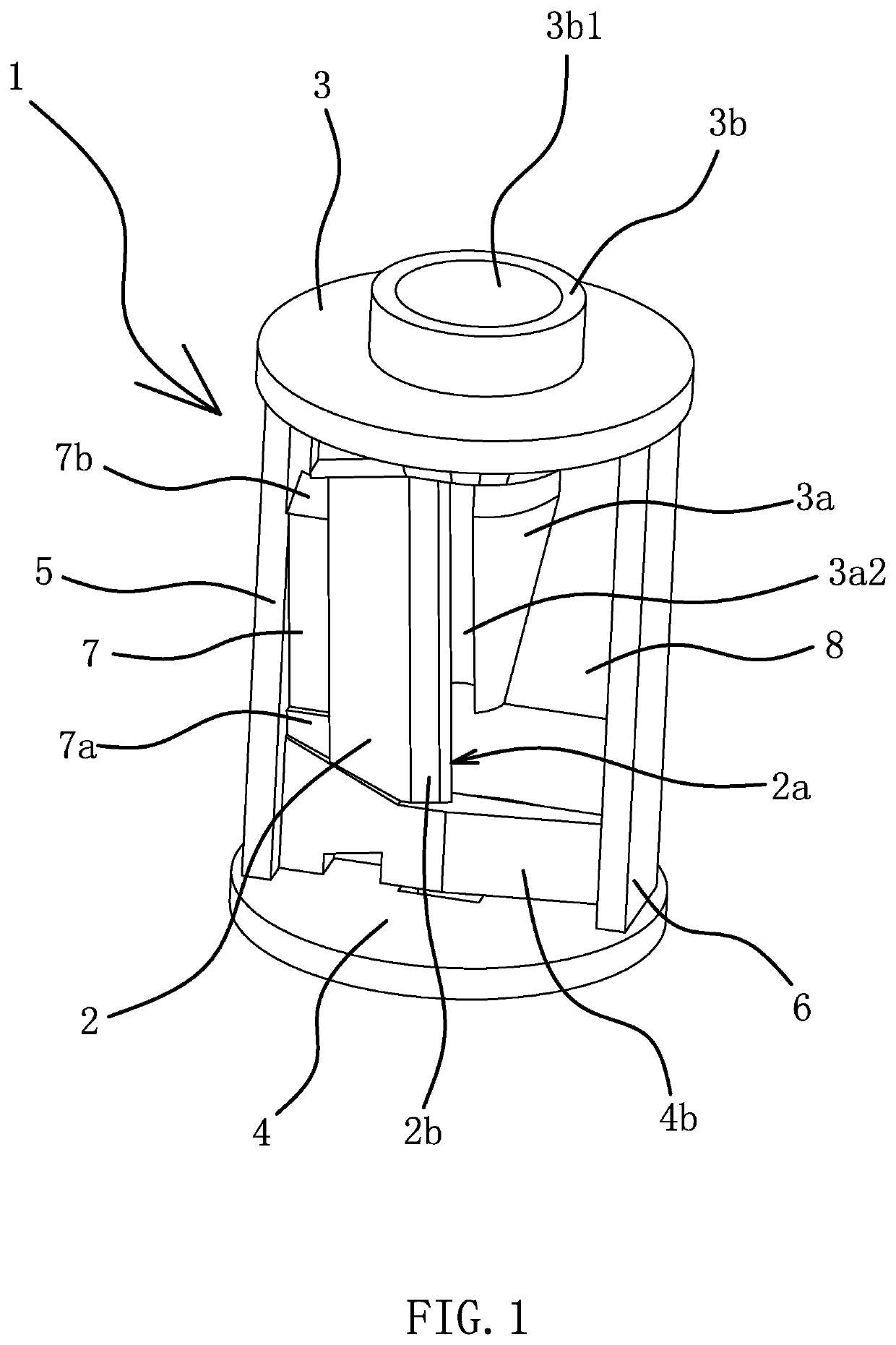
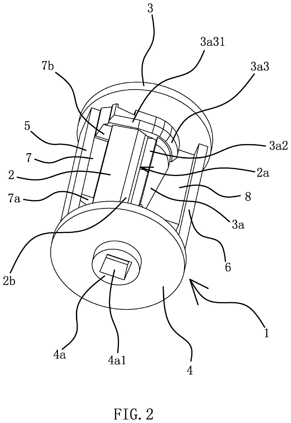
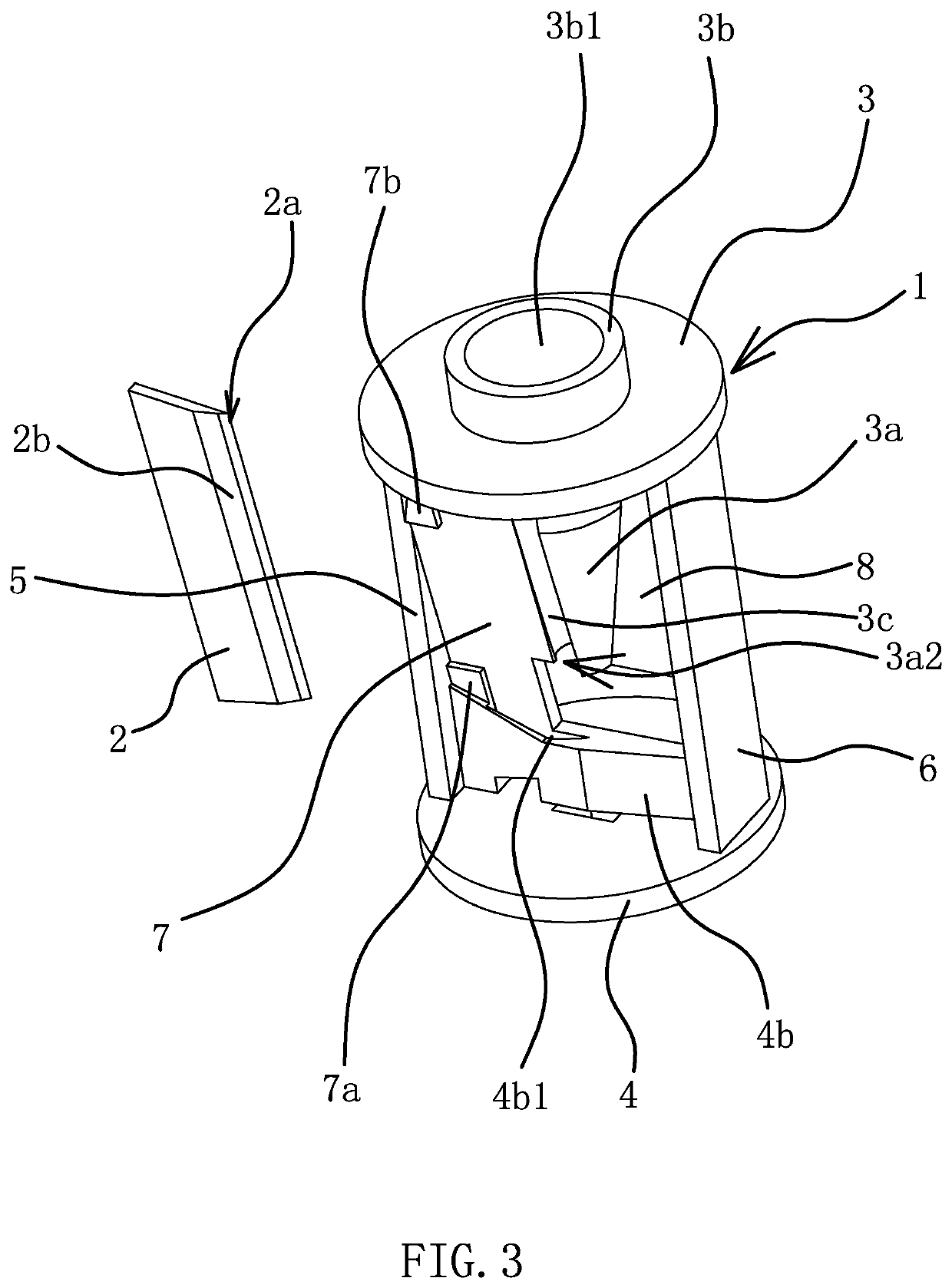
[0047]As shown in FIG. 1, FIG. 2, and FIG. 6, one embodiment of a pencil sharpener assembly comprises a frame 1 and a blade 2, the blade 2 is made of a ceramic material. The blade 2 has an elongated sheet shape, and one side of the blade 2 is disposed with a blade edge 2a. The frame 1 is an integrated structure, the frame 1 comprises a lower plate 4, an upper plate 3 disposed oppositely to the lower plate 4, and a first support plate 5 and a second support plate 6 which are both fixedly connected between the upper plate 3 and the lower plate 4, and the first support plate 5 and the second support plate 6 are disposed oppositely to each other. A lower end surface of the lower plate 4 is disposed with a protruded coupler 4a, and the coupler 4a is provided with a square coupling hole 4a1. The disposition of the coupling hole 4a1 is mainly provided for inserting a rotating shaft end of a motor when the pencil sharpener assembly is used in an electric pencil sharpener, so that the rotati...

embodiment 2

[0058]The structure and the principles of this embodiment are basically the same as those of the first embodiment. The differences lie in that, as shown in FIG. 12, in this embodiment, a bolster strip 10 is disposed between an outer side wall of the outer bulge 3a3 and an outer side wall of the positioning portion 4b, and an inner side surface of the bolster strip 10 is attached to an outer side surface of the blade 2. By having the bolster strip 10 disposed between the outer side wall of the outer bulge 3a3 and the outer side wall of the positioning portion 4b, and the inner side surface of the bolster strip 10 attached to the outer side surface of the blade 2, the fixing effect of the ceramic-made blade 2 on the frame 1 can be further enhanced.

[0059]The specific embodiments described herein are merely illustrative of the spirit of the present invention. Technical personnel skilled in the art to which the present invention pertains can make various modifications or additions to the...


PUM


Abstract

A pencil sharpener assembly comprising a frame and a blade, the blade having an elongated sheet shape, one side of the blade being disposed with a blade edge, the frame being disposed with a pencil chamber, the blade being disposed along an axial direction of the pencil chamber and the blade edge of the blade being located in the pencil chamber, the blade being made of a ceramic material, the frame being disposed with a first positioning groove and a second positioning groove, the first positioning groove and the second positioning groove being oppositely disposed, a first end of the blade being inserted into the first positioning groove, and a second end of the blade being inserted into the second positioning groove. It has the advantages of being applicable to ceramic-made blades and the blade is not easy to fracture.

Description

RELATED APPLICATIONS[0001]This application claims priority to China Patent Application No. CN201810300814.5 filed Apr. 4, 2018.[0002]The applications and all patents, patent applications, articles, books, specifications, other publications, documents, and things referenced herein are hereby incorporated herein in their entirety for all purposes. To the extent of any inconsistency or conflict in the definition or use of a term between any of the incorporated publications, documents, or things and the text of the present document, the definition or use of the term in the present document shall prevail.BACKGROUND OF THE INVENTIONField of Invention[0003]The present invention belongs to the technical field of machinery and relates to a pencil sharpener assembly.Related Art[0004]Pencil sharpener is a tool for sharpening pencils, it is widely used for daily study or work because it is convenient to use. In order to improve its convenience, many types of electric pencil sharpeners have been...

Claims


Application Information

Patent Timeline
Patent Type & Authority Patents(United States)
IPC IPC(8): B43L23/08B43L23/00B26D1/00
CPCB43L23/08B43L23/004B43L23/008B26D2001/002B43L23/00
Inventor LIN, XIASEN
Owner SUNWOOD HLDG GROUP
Why Eureka
Try Eureka