Flap support mechanism—C bar

a technology of support mechanism and flap, applied in mechanical devices, transportation and packaging, gearing, etc., can solve the problems of increasing aircraft weight, cost and complexity, and achieve the effect of increasing camber

Active Publication Date: 2021-06-15
THE BOEING CO
View PDF3 Cites 0 Cited by
  • Summary
  • Abstract
  • Description
  • Claims
  • Application Information

AI Technical Summary

Benefits of technology

[0004]Exemplary embodiments provide a trailing edge flap actuation mechanism having a flap drive link with a first end pivotally coupled to a fore flap structure of a flap and a second end pivotally coupled to an underwing support structure. An aft tension link has a leading end pivotally coupled proximate an aft end of the underwing support structure and a trailing end coupled to a mid-section structure of the flap. An actuator, when actuated, rotates the flap drive link about a first pivot axle to move the flap between a retracted position and a deployed lowered position. The actuator, including a ball-screw drive shaft with a universal joint, is positioned in a cove above the underwing support structure whereby the extent that the underwing support structure protrudes below the wing is reduced.
[0005]The implementations herein provide a method for deployment of a flap wherein a flap drive link is pivotally engaged with a drive axle to a fore flap structure with the flap drive link rotatable about a first pivot axle in an underwing support structure. A ball nut pivotally carried by the flap drive link is engaged with a ball screw shaft of an actuator. The flap drive link is rotated from an initial acute drive angle. An aft tension link is rotatably engaged to an aft end of the underwing support structure with a second pivot axle at an obtuse initial drag angle and pivotally engaged at a trailing end to a mid-section structure of the flap with a drive reaction axle. A connector bar between the drive axle and reaction axle is created with the flap structure. Rotating the flap drive urges the drive axle and, through the connector bar the reaction axle, to rotate the aft tension link from the initial obtuse drag angle for enhanced increasing camber.

Problems solved by technology

Prior art solutions for large commercial aircraft may have high actuator loads which require complex mechanical arrangements and large actuators or transmission systems which may increase aircraft weight, cost and complexity.

Method used


Image

  • Flap support mechanism—C bar
  • Flap support mechanism—C bar
  • Flap support mechanism—C bar

Examples


Embodiment Construction

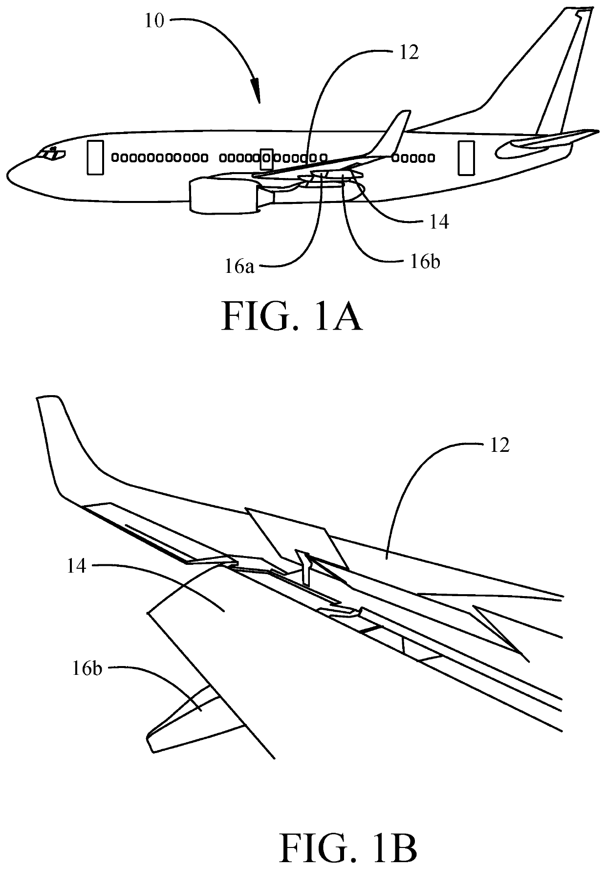
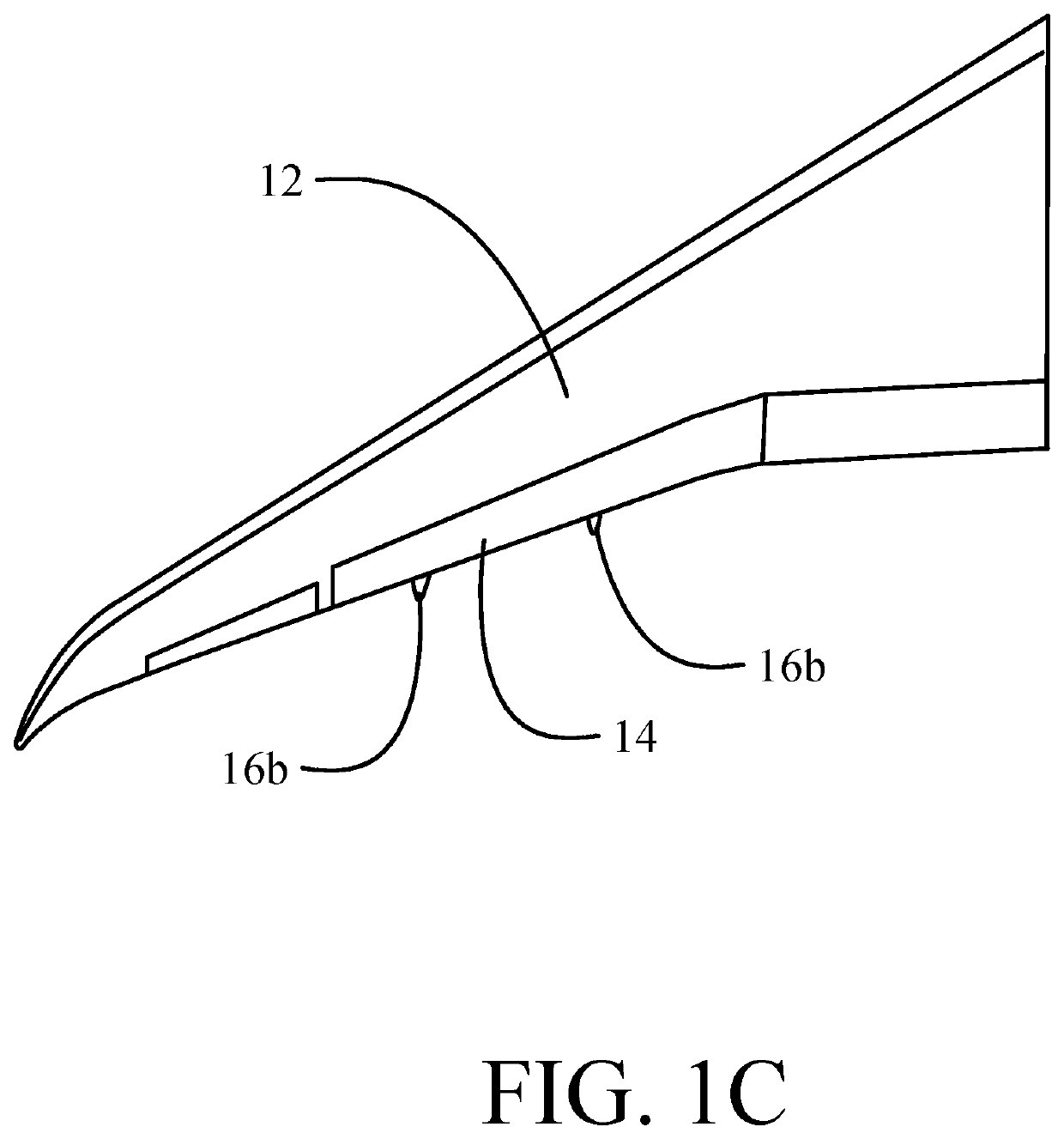
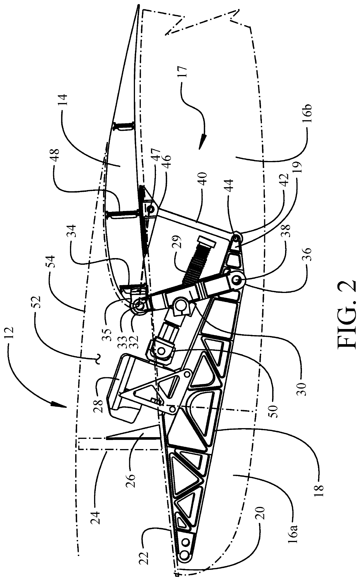
[0016]The implementations described herein provide a trailing edge flap mechanism which maintains streamwise motion employing underwing beams incorporating a stacked actuator arrangement. The streamwise motion simplifies the interaction between the inboard and outboard flap, which both travel straight aft without interference, to simplify seal design. The stacked actuator makes use of the space already reserved for the flap support with the actuator gearbox residing in the trailing edge cove thereby reducing fairing depth. A “C” bar configuration of a flap drive link coupled to a fore flap structure and pivoting on an underwing support structure and an aft tension link coupled to a mid-section flap structure and pivoting on an aft end of the underwing support structure allows the actuator to be a linear ball screw with greater efficiency and less weight than a rotary actuator. The “C” bar mechanism also enables trailing edge variable camber (TEVC) to be incorporated. The trailing ed...


PUM


Abstract

A trailing edge flap actuation mechanism has a flap drive link with a first end pivotally coupled to a fore flap structure of a flap and a second end pivotally coupled to an underwing support structure. An aft tension link has a leading end pivotally coupled proximate an aft end of the underwing support structure and a trailing end coupled to a mid-section structure of the flap. An actuator, when actuated, rotates the flap drive link about a first pivot axle to move the flap between a retracted position and a deployed lowered position. The actuator, including a ball-screw drive shaft having a universal joint, is positioned in a cove above the underwing support structure whereby the extent that the underwing support structure protrudes below the wing is reduced.

Description

[0001]This application is copending with application Ser. No. 16 / 172,748 filed on Oct. 27, 2018 and entitled WING FLAP MECHANISM FOR HIGH FOWLER, DROOPING SPOILERS AND HIGH EFFICIENCY.BACKGROUND INFORMATIONField[0002]Embodiments of the disclosure relate generally to the field of aircraft flap extension systems and, more particularly to a trailing edge flap mechanism employing a first flap link coupled to a fore flap structure and pivoting on an underwing support structure and a second flap link coupled to a mid-section flap structure an pivoting on an aft end of the underwing support structure for increased camber earlier in flap stroke movement.Background[0003]Aircraft employ flaps which increase camber of the wings for enhanced aerodynamic efficiency in take-off and landing. Various mechanical arrangements have been developed to deploy the flaps from retracted to extended positions. Prior art solutions for large commercial aircraft may have high actuator loads which require comple...

Claims


Application Information

Patent Timeline
Patent Type & Authority Patents(United States)
IPC IPC(8): B64C3/38B64C5/10F16H21/44F16H51/00B64C5/08F16H25/22
CPCB64C5/10B64C3/38B64C5/08F16H21/44F16H25/2204F16H51/00B64C9/18
Inventor TSAI, KEVIN R.DAHL, BRUCE A.SANTINI, GREGORY M.JOHNSON, KYLE A.SAKURAI, SEIYAAMOROSI, STEPHEN R.
Owner THE BOEING CO
Why Eureka
Try Eureka