Concrete slab lifting system

a technology of concrete and lifting system, which is applied in the direction of lifting devices, foundation engineering, buildings, etc., can solve the problems of inability to work with the slab below, no support for the jack to prevent toppling, and inapplicability of the suspension mechanism of the prior ar

Inactive Publication Date: 2006-06-08
JACKING SYST
View PDF7 Cites 12 Cited by
  • Summary
  • Abstract
  • Description
  • Claims
  • Application Information

AI Technical Summary

Benefits of technology

[0006] In one aspect, the invention provides a system of lifting and conveying a concrete slab and/or associated works, wherein the slab having an area includes a plurality of apertures therethrough said slab area, the apertures being provided with a respective jack, said jack at least comprising at least one shaft having a portion passing through said aperture and contacting a lower support means, means for connecting said slab to said shaft, the connection means incorporating at lea...

Problems solved by technology

However in practice this system was found to have many problems that stimulated the development of the current system of this application.
The suspension means of the prior art was found to be impractical whereby the connection to the slab below was not workable due to the high jacking point loads involved creating seriously weakened slab portions.
Also during use of the system when the jack was disconnected from each floor, there was no means of support for the jack to prevent toppl...

Method used


Image

  • Concrete slab lifting system
  • Concrete slab lifting system
  • Concrete slab lifting system

Examples


Embodiment Construction

[0095] The invention can be understood by reference to FIGS. 1 to 16 whereby in summary FIGS. 1-10 show the synchronised system, FIG. 11 shows the jack and FIGS. 12-16 show the scaffolding system. The following numbering sequence for FIGS. 12-16 are to be considered separately, from the other figures.

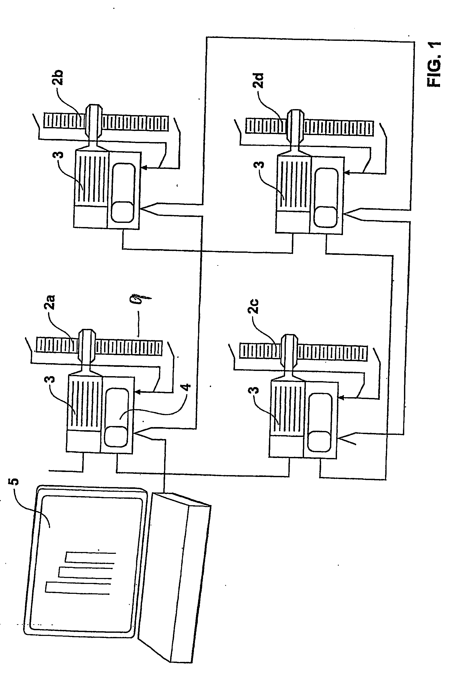
[0096] For simplicity only four jacks 2A-2D are shown connected to a central computer 5. Each jack is a screw jack driven by an electric motor 3, which is controlled by variable speed drive 4. Typically each motor can be a 0.75-1.5 kW, four pole, 50 Hz, flange mounted 400 volts, brake motor. Each motor 3 will be driven by a three phase power supply typically 400 volts at 100 amps. Each motor is controlled by a central computer 5.

[0097] The system can provide a synchronised position control through a system controller of a number of motors 3. One control parameter is position synchronisation between all the jacks. This makes use of variable speed control of the individual jack motors, ...


PUM


Abstract

The invention provides a system and method of lifting and conveying a concrete slab and/or associated works. The slab has an area includes a plurality of apertures therethrough. A jack at least comprising a shaft having a portion passes through the aperture and contacts a lower support means. The system includes a means for connecting the slab to the shaft. The connection means incorporates at least one supporting member connecting the slab to the shaft. Each supporting member passes through another said aperture and engages the slab. Also included is a means for effecting longitudinal travel of said supporting means along said shaft, resulting in the raising or lowering of said slab. Position sensors are associated with each jack and the system includes a means for communicating and controlling between each jack and one or more main controllers. There is also provided a jack for lifting a concrete slab which includes a shaft and ball screw, a drive assembly, a hanger assembly, a support device. The drive assembly drives the ball screw to raise the shaft with respect to the hanger assembly such that the jack has climbed the support device supports the shaft to prevent toppling and provide stability.

Description

TECHNICAL FIELD OF THE INVENTION [0001] This invention relates to the lifting of pre-cast concrete slabs and has particular application to a method and apparatus for constructing a multi-storey building. BACKGROUND OF THE INVENTION [0002] A jacking system as developed by the inventor of the present invention, in U.S. Pat. No. 5,644,893, covered a system for constructing multi-storey buildings. The system comprised extendible props (or jacks) being retractable and having cable suspension means. However in practice this system was found to have many problems that stimulated the development of the current system of this application. [0003] The suspension means of the prior art was found to be impractical whereby the connection to the slab below was not workable due to the high jacking point loads involved creating seriously weakened slab portions. Also during use of the system when the jack was disconnected from each floor, there was no means of support for the jack to prevent toppling...

Claims


Application Information

Patent Timeline
IPC IPC(8): E04G21/14B66F3/08B66F3/46E04B1/35
CPCB66F3/08B66F3/46E04B1/3511
Inventor NEIGHBOURS, GREGORY JOHN
Owner JACKING SYST
Why Eureka
Try Eureka