Optical fiber ceramic core automatic grinder and automatic grinding method

A ceramic ferrule and grinding machine technology, which is applied to machine tools, grinders, and grinding/polishing equipment suitable for grinding workpiece planes, can solve the problem of uneven grinding of the end face of optical fiber ceramic ferrules, difficult to control down pressure, and difficult to control. Meet the 3D requirements of the end face of the fiber ceramic ferrule, and achieve the effect of avoiding instability, high precision and high grinding quality

Inactive Publication Date: 2009-04-22
SHENZHEN XIANGTONG PHOTOELECTRIC TECH
View PDF2 Cites 30 Cited by
  • Summary
  • Abstract
  • Description
  • Claims
  • Application Information

AI Technical Summary

Problems solved by technology

[0004] However, the existing grinding equipment and methods have the following disadvantages: when the fiber optic ceramic ferrule is ground to a certain extent, it is necessary to manually press down the grinding tool to ensure that the fiber optic ceramic ferrule has a certain grinding pressure. However, such The downward pressure is often difficult to control, resulting in uneven grinding of the end face of the fiber optic ceramic ferrule, and it is difficult to meet the 3D requirements for the end face of the fiber optic ceramic ferrule, that is, the spherical radius, which refers to the spherical radius of the ceramic end face after grinding, and its standard value It is between 10-25MM (millimeters); the height of the optical fiber refers to the distance between the optical fiber installed in the ceramic ferrule and the ceramic surface next to it after grinding, and its standard value is between (-100-100NM) (nanometers); the apex Offset, its standard value is between 0-50UM (microns)

Method used


Image

  • Optical fiber ceramic core automatic grinder and automatic grinding method
  • Optical fiber ceramic core automatic grinder and automatic grinding method
  • Optical fiber ceramic core automatic grinder and automatic grinding method

Examples


Embodiment Construction

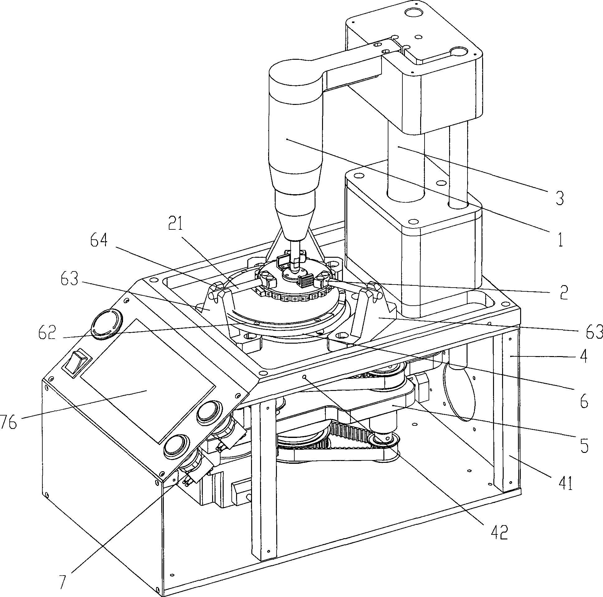
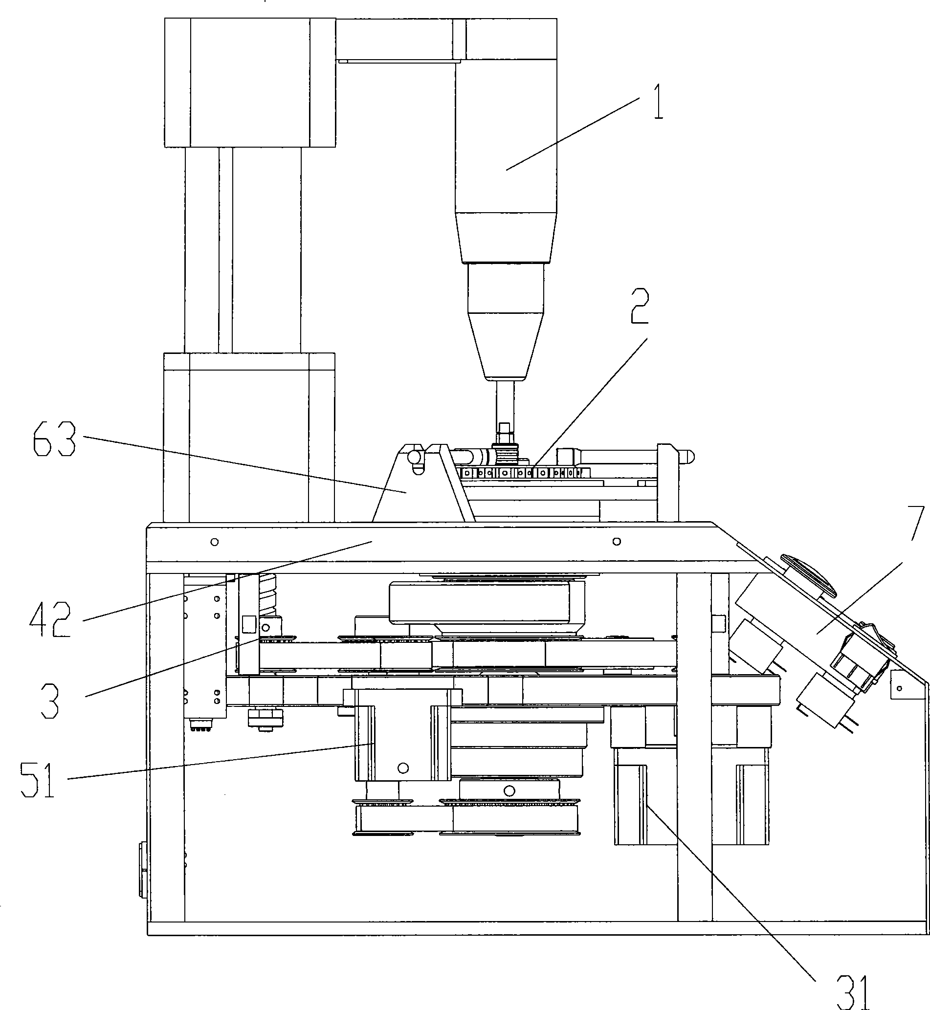
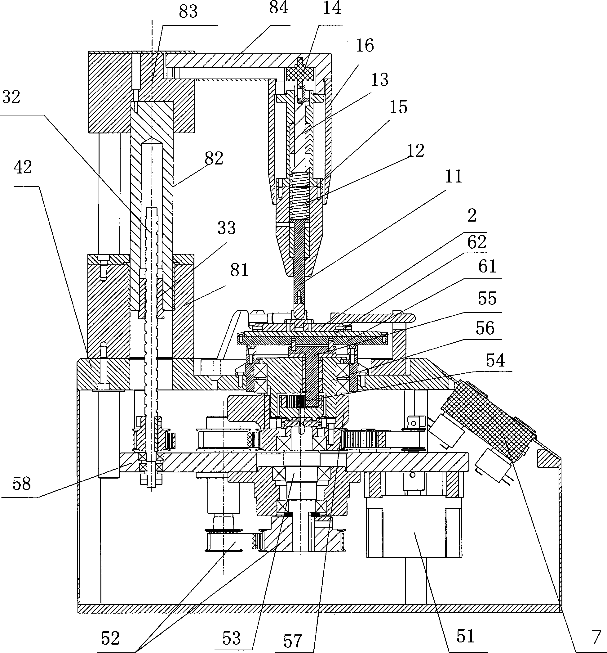
[0031] Such as Figure 1 to Figure 4 As shown, it is an embodiment of the fiber ceramic ferrule automatic grinding machine of the present invention, comprising a frame 4, a power system 5 installed on the frame 4, a grinding system 6 driven by the power system 5, and a power system installed on the frame 4 The upper lifting system 3, the pressure system 1 driven up and down by the lifting system 3, and the control system 7 that controls the lifting system 3 to rise or fall according to the pressure change of the pressure system 1 and / or the change of the grinding time.

[0032] In this embodiment, the frame 4 includes a plurality of columns 41 arranged vertically, and an upper base plate 42 installed on the columns 41 . Further, a connecting base plate is installed on the lower side of the upper base plate 42 for installation of the power system 5 and the lifting system 3 .

[0033] The power system 5 includes a drive motor (brushless DC motor 51 ) and a transmission mechanis...


PUM


Abstract

The invention relates to an automatic grinder for an optical fiber ceramic insert core and an automatic grinding method. The grinder comprises a stander, a power system arranged on the stander, a grinding system extended out of the stander and driven by the power system, a lifting system arranged on the stand, a pressure system driven by the lifting system to move up and down and a control system, wherein the pressure system and the grinding system are arranged oppositely. The automatic grinding method is as follows: an optical fiber ceramic insert core to be processed is arranged on the grinding system, and the lifting system is controlled to drive the pressure system to compress the fiber ceramic insert core to be processed; the grinding system begins working to grind the lower end face of the fiber ceramic insert core to be processed; and through monitoring pressure change of the pressure system, the control system controls ascending or descending of the lifting system according to the pressure change and/or change of grinding time, to further compress or loosen the optical fiber ceramic insert core, so as to avoid defects of instability and unevenness brought by manual operation. The automatic grinding method has the advantages of accurate control, high precision, safety and reliability.

Description

technical field [0001] The invention relates to grinding equipment, more specifically, to an automatic grinding machine and an automatic grinding method for optical fiber ceramic ferrules. Background technique [0002] The connection end face of the traditional optical fiber ceramic ferrule needs to be ground into a certain shape, so that the transmitted optical signal can pass through the connection smoothly without excessive photometric attenuation. [0003] The current processing of fiber optic ceramic ferrules is: installing the fiber optic ceramic ferrules on the grinding tool, so that multiple fiber optic ceramic ferrules can be clamped by the grinding tool at the same time for end face grinding. Then, the grinding tool is placed on the working disc of the grinding system of the grinding equipment, and the power system drives the working disc to rotate and revolve. At the same time, operate the pressing device by hand or manually to press the grinding tool, so that th...

Claims


Application Information

Patent Timeline
Patent Type & Authority Applications(China)
IPC IPC(8): B24B7/16B24B7/22
Inventor 王光辉谭莉陈永清
Owner SHENZHEN XIANGTONG PHOTOELECTRIC TECH
Why Eureka
Try Eureka