Braking device for a hydraulic motor vehicle braking system having a ball screw drive

a technology of hydraulic motor vehicles and braking devices, which is applied in the direction of braking systems, vehicle sub-unit features, transportation and packaging, etc., can solve the problems of high production costs, complex boom stage, and high production costs of hollow spindles, and achieve the effect of reducing the number of components

Active Publication Date: 2019-03-28
CONTINENTAL TEVES AG & CO OHG
View PDF5 Cites 12 Cited by
  • Summary
  • Abstract
  • Description
  • Claims
  • Application Information

AI Technical Summary

Benefits of technology

[0007]An aspect of the invention is an improved braking device of the type stated at the outset which, while avoiding the abovementioned disadvantages, is of as compact, weight-saving and space-saving construction as possible, nevertheless allows effective direct action on the cylinder piston in the event of failure of the booster stage and, during normal operation, allows comfortable haptic feedback at the pedal.

Problems solved by technology

However, direct action by the driver must also be implemented—the possibility of actuating the brake directly with the actuating or foot force of the driver in the event of a malfunction or failure of the booster stage.
It is regarded as a disadvantage that, the construction of the booster stage is complex overall and that production is expensive.
Moreover, the production of a hollow spindle is very expensive.

Method used


Image

  • Braking device for a hydraulic motor vehicle braking system having a ball screw drive
  • Braking device for a hydraulic motor vehicle braking system having a ball screw drive
  • Braking device for a hydraulic motor vehicle braking system having a ball screw drive

Examples


Embodiment Construction
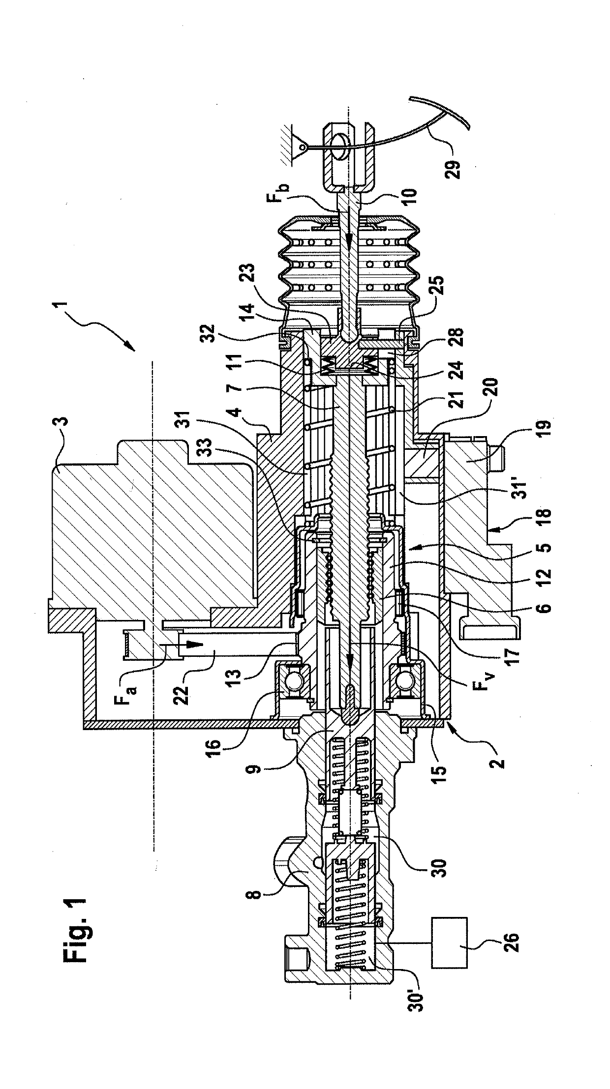
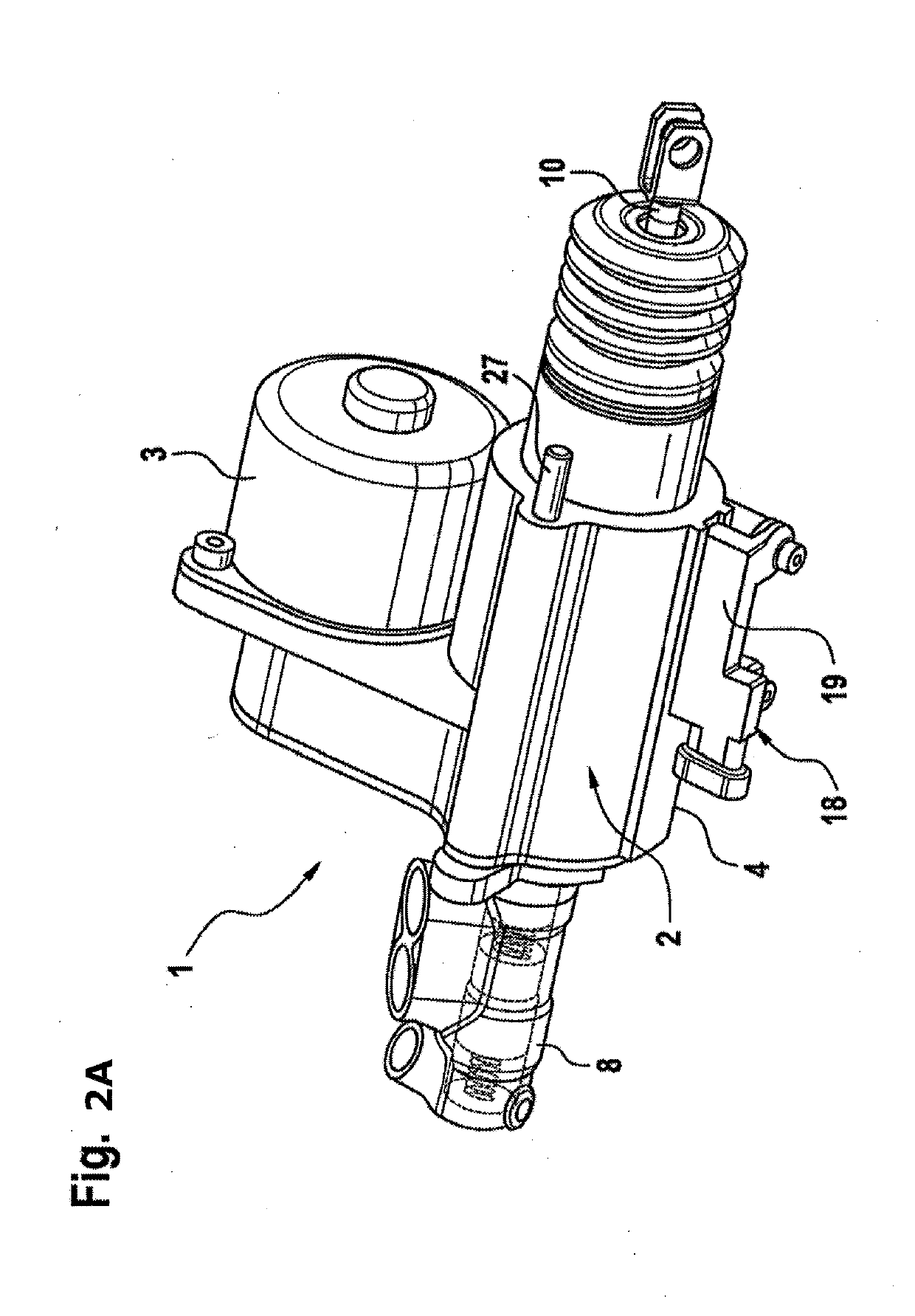
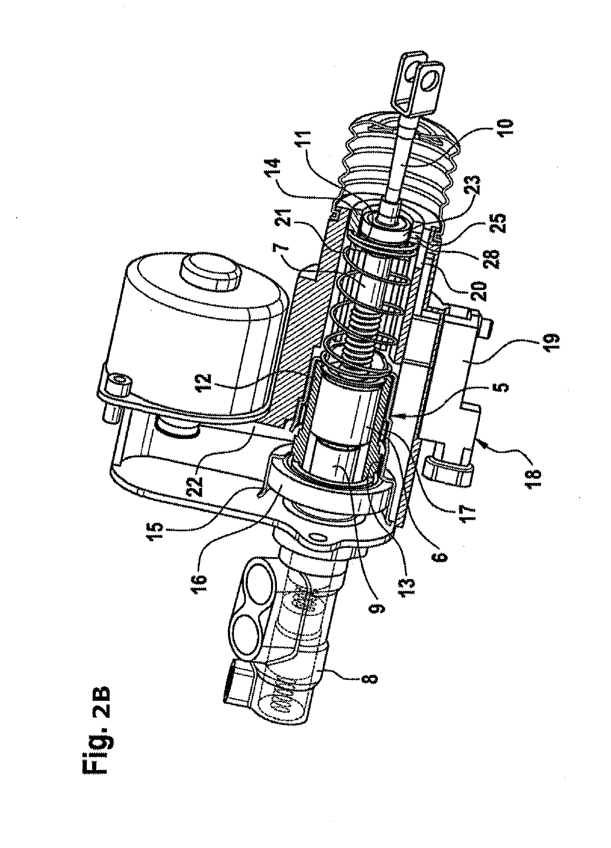
[0027]FIG. 1:

[0028]The braking device 1 according to an aspect of the invention essentially comprises a booster stage 2, which is driven by an electric-motor drive unit 3 and on which a brake master cylinder 8 is mounted. In the example under consideration, it is a tandem brake master cylinder of plunger-type construction, although other types of brake master cylinder can also likewise be used within the scope of an aspect of the invention.

[0029]A cylinder piston 9 is mounted in the brake master cylinder 8 in such a way that it can be moved in a linear manner in the axial direction, said piston producing brake pressure through its movement in pressure chambers 30, 30′, which are filled with pressure medium and are connected to wheel brakes. An optionally present pressure sensor 26 records the current brake pressure.

[0030]The booster stage 2 has a booster housing 4, which is preferably produced from plastic and in which a ball screw drive 5 is arranged.

[0031]By means of a toothed bel...


PUM


Abstract

A braking device for a hydraulic motor vehicle braking system having an electromechanically driven booster stage and a ball screw drive. In order to provide a braking device which is of particularly compact, cost-effective and weight-saving construction and has short pedal strokes, and an easily adjustable pedal characteristic curve, at the same time enabling effective direct action in case of failure of the booster stage and comfortable haptic feedback at the pedal during normal operation, the actuating force from a piston rod is introduced into the spindle, wherein the piston rod can be moved axially to a limited extent relative to the spindle and a spring element is inserted in the flow of force of the actuating force between the piston rod and the spindle, which spring is compressed axially when the actuating force is introduced.

Description

CROSS REFERENCE TO RELATED APPLICATIONS[0001]This application is the U.S. National Phase Application of PCT International Application No. PCT / EP2017 / 061330, filed May 11, 2017, which claims priority to German Patent Application No. 10 2016 208 348.1, filed May 13, 2016, the contents of such applications being incorporated by reference herein.FIELD OF THE INVENTION[0002]The invention relates to a braking device for a hydraulic motor vehicle braking system.BACKGROUND OF THE INVENTION[0003]For hydraulic braking systems on motor vehicles, the use of braking devices which have a brake master cylinder with a cylinder piston that can be moved in a linear manner to produce brake pressure and have an electromechanical booster stage that acts on the cylinder piston is known. In this case, the booster stage is driven by a drive unit having a rotating drive shaft and, to convert the rotary motion of the drive shaft into a translational motion, uses a ball screw drive.[0004]Units of this kind ha...

Claims


Application Information

Patent Timeline
Patent Type & Authority Applications(United States)
IPC IPC(8): B60T11/18B60T11/20B60T13/74B60T7/04B60T7/12
CPCB60T11/18B60T11/20B60T13/745B60T7/042B60T7/12F16D2121/24B60T7/04B60T13/74B60Y2400/81
Inventor BACH, UWEHOFFMANN, JENSGADKE, MARTINVON HAYN, HOLGERSEFO, AHMEDMESSNER, ADRIANRITTER, WOLFGANG
Owner CONTINENTAL TEVES AG & CO OHG
Why Eureka
Try Eureka