
Automatic clearing device for drill bit winding chips and operation control method of automatic clearing device

A technology for automatic removal of drill bits, which is applied in the direction of manufacturing tools, metal processing machinery parts, maintenance and safety accessories, etc., can solve the problems of drill bit damage, affecting processing efficiency, and easy damage of drill bits, so as to reduce the probability of damage, improve efficiency, and automate high degree of effect

Active Publication Date: 2016-11-09
德州德隆(集团)机床有限责任公司
View PDF6 Cites 12 Cited by
  • Summary
  • Abstract
  • Description
  • Claims
  • Application Information

AI Technical Summary

Problems solved by technology

[0004] Aiming at the problems of the current drilling equipment when drilling in batches, the swarf on the drill bit will cause the drill bit to be damaged quickly and affect the processing efficiency. Low efficiency caused by entanglement, easy damage to the drill bit, etc.

Method used


Image

  • Automatic clearing device for drill bit winding chips and operation control method of automatic clearing device
  • Automatic clearing device for drill bit winding chips and operation control method of automatic clearing device
  • Automatic clearing device for drill bit winding chips and operation control method of automatic clearing device

Examples


Embodiment Construction

[0026] Hereinafter, exemplary embodiments of the present disclosure will be described in more detail with reference to the accompanying drawings. Although exemplary embodiments of the present disclosure are shown in the drawings, it should be understood that the present disclosure may be implemented in various forms and should not be limited by the embodiments set forth herein. On the contrary, these embodiments are provided to enable a more thorough understanding of the present disclosure and to fully convey the scope of the present disclosure to those skilled in the art.

[0027] In the description of the present invention, it should be understood that the terms "longitudinal", "lateral", "upper", "lower", "front", "rear", "left", "right", "vertical", The orientation or positional relationship indicated by "horizontal", "top", "bottom", "inner", "outer", etc. is based on the orientation or positional relationship shown in the drawings, and is only for the convenience of describ...


PUM


Abstract

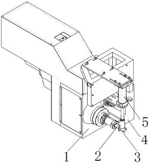
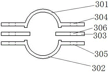
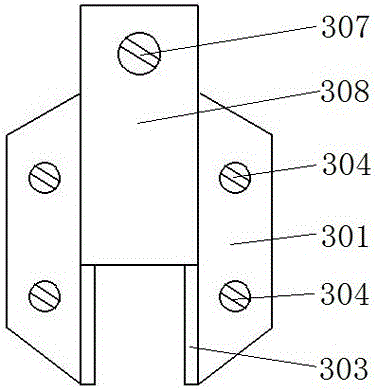
The invention relates to the fields of machining and manufacturing and particularly relates to an automatic clearing device for drill bit winding chips and an operation control method of the automatic clearing device. The automatic clearing device comprises a drill rod box, a tool, a chip scraper, a feeding sliding table and an air cylinder, wherein the drill rod box is mounted at the bottom side of the front of the device and is provided with the tool; the feeding sliding table is provided with a ball screw driving the drill rod box to make cutting and feeding motion; an upper fixed plate and a lower fixed plate are arranged above the feeding sliding table, the air cylinder is mounted between the upper fixed plate and the lower fixed plate; and the tail end of a telescopic rod of the air cylinder is provided with the chip scraper. The device is of a rapid chip removal structure designed for solving the problem of drill bit winding chips generated during efficient machining of a numerical control drilling machine, the chip scraper at the upper end of a drill bit is driven by the air cylinder with double functions so as to rapidly move to the root of the drill bit, a servo feeding system of a machine tool drives the drill bit to rapidly retreat, and iron chips wound on the drill bit are rapidly scrapped by using the chip scraper. A numerical control system controls a pneumatic system to drive the air cylinder with double functions to finish all actions of chip scrapping, so that the automation degree is high.

Description

Technical field [0001] The invention relates to the field of mechanical processing and manufacturing, in particular to an automatic chip removal device and operation control method for drill bits. Background technique [0002] During the drilling process of the drill bit, a large amount of drill cuttings are generated and continuously discharged. Some of the drill cuttings will flow out along the spiral groove of the drill bit and be discharged by lifting the drill bit by themselves, but some are easily entangled on the drill bit or accumulated Attached to the groove of the drill bit, the drill chips attached to the drill bit are generally at a high temperature and sharp. If they are not removed in time, they will rotate synchronously with the drill bit, which can easily hurt the operator and cause the drilling operation. Because of disturbance. In order to avoid the danger of drill cuttings, the operator must be forced to stop the drilling operation to remove the drill cuttings...

Claims


Application Information

Patent Timeline
Patent Type & Authority Applications(China)
IPC IPC(8): B23Q11/02
CPCB23Q11/02
Inventor 李敬伟曹振松林晶伟张文强刘铸
Owner 德州德隆(集团)机床有限责任公司
Learn More