Radar level gauge system with dielectric antenna

a technology of dielectric antenna and level gauge, which is applied in the direction of engine lubrication, liquid/fluent solid measurement, reradiation, etc., can solve the problems of product monitoring and/or measurement being often flammable, and achieve efficient and convenient process sealing, facilitate sealing deformation and/or flow of material, and facilitate sealing

Active Publication Date: 2021-06-29
ROSEMOUNT TANK RADAR
View PDF18 Cites 4 Cited by
  • Summary
  • Abstract
  • Description
  • Claims
  • Application Information

AI Technical Summary

Benefits of technology

[0018]By “conductively separate” the transceiver from the conductive antenna housing should be understood to prevent flow of charge between the transceiver and the conductive antenna housing. An equivalent expression that is sometimes used is “galvanically separate”.
[0043]The purpose of the microwave absorbing structure is to reduce the occurrence of unwanted side lobes.

Problems solved by technology

Since products to be monitored and / or measured are often flammable, special safety requirements exist for equipment, such as radar level gauge systems or at least parts thereof that are positioned within a so-called hazardous area.

Method used


Image

  • Radar level gauge system with dielectric antenna
  • Radar level gauge system with dielectric antenna
  • Radar level gauge system with dielectric antenna

Examples


first embodiment

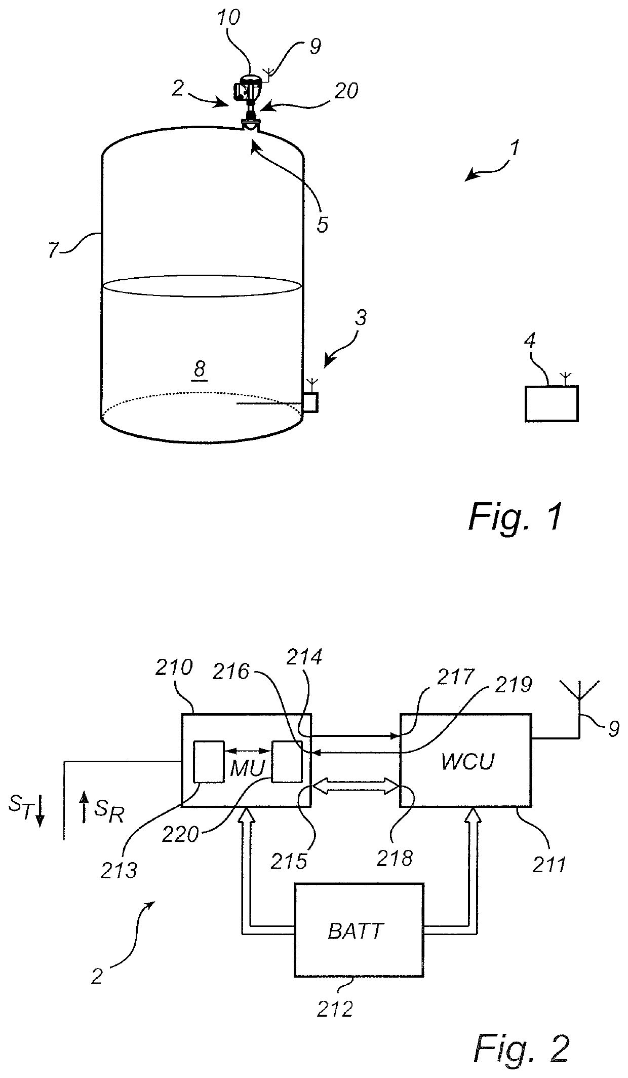
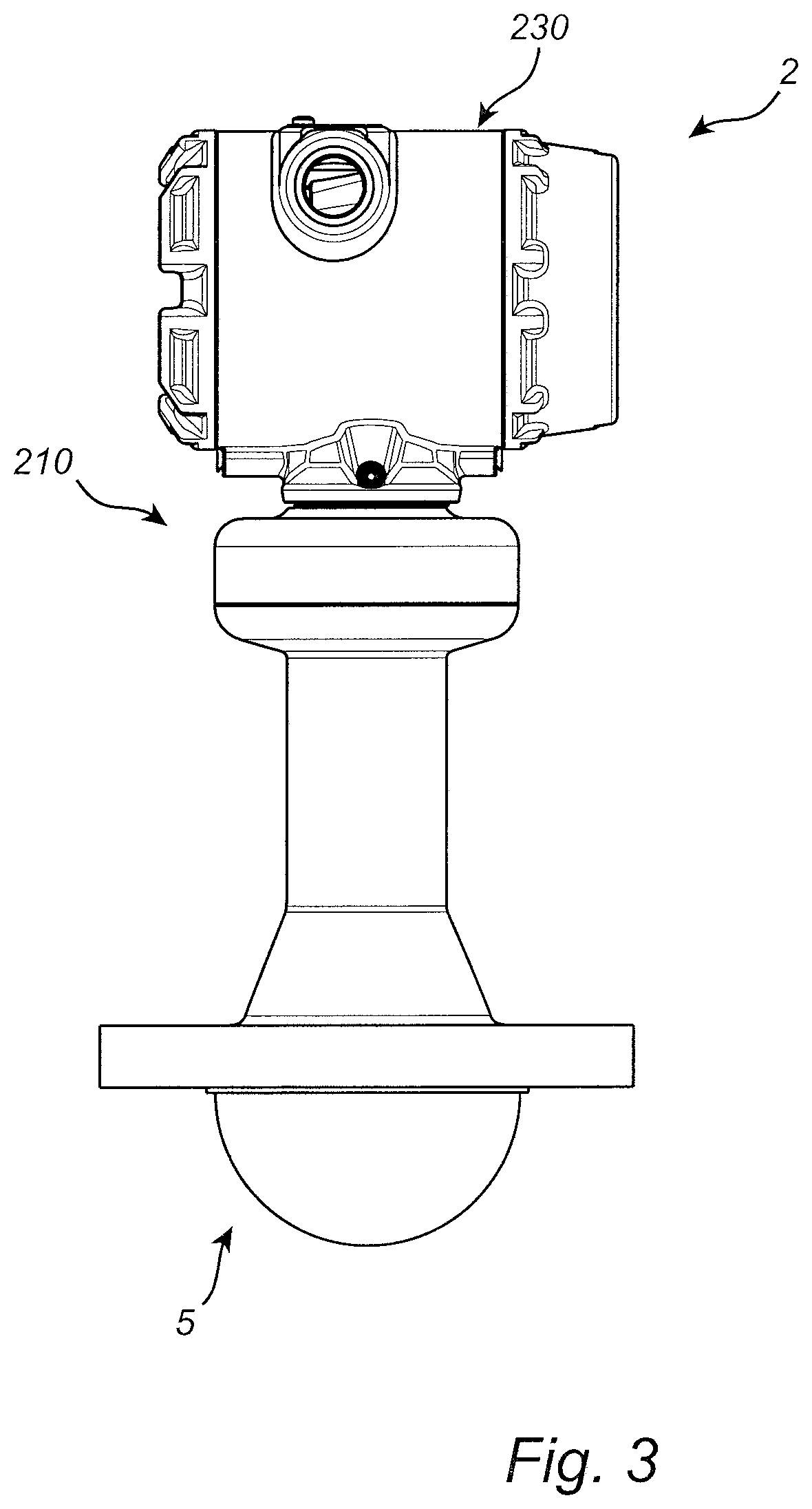
[0061]FIG. 3 is a side view of the radar level gauge system 2 in FIG. 1. Referring to FIG. 3, the radar level gauge system 2 comprises measurement unit 210, communication unit 230, and antenna arrangement 5. Referring to the description provided above in relation to FIG. 1 and FIG. 2, the measurement unit 210 comprises the transceiver 213, the measurement processor 220, and the feed-through 20; and the communication unit 230 comprises the wireless communication unit 211 and the battery 212.

[0062]The feed-through may advantageously form part of an explosion-proof enclosure, and, as will be described in more detail further below, the antenna galvanically separates the transceiver 213 from the interior of the tank to provide intrinsic safety, and additionally provides a sealing connection to the interior of the tank 7.

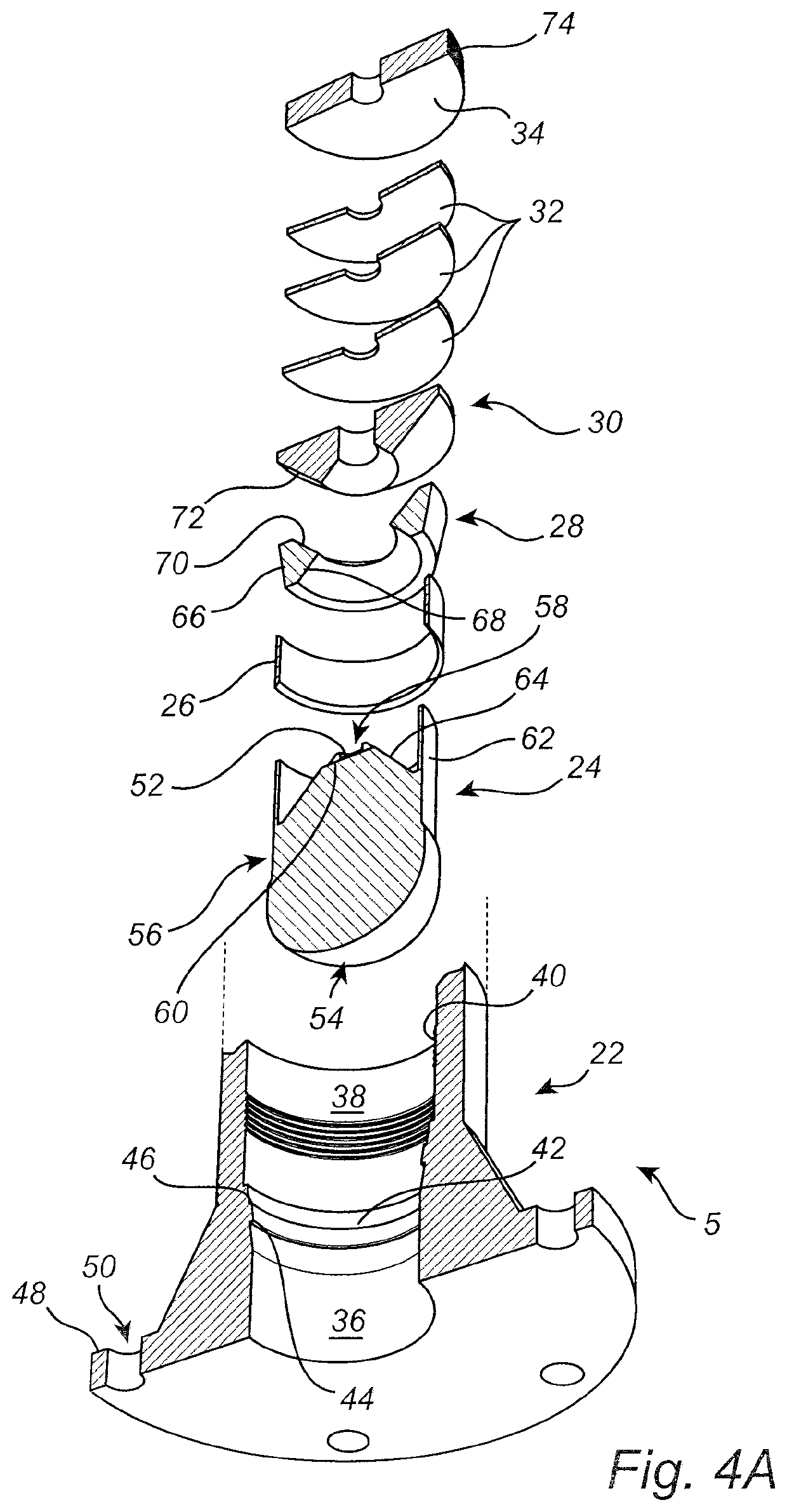
[0063]In the following, the antenna arrangement 5, and the galvanic separation and sealing provided by the antenna arrangement 5 will be described in greater detail with ...

second embodiment

[0075]FIG. 5 is a partly cut-out side view of the radar level gauge system 2 in FIG. 1. Referring to FIG. 5, the radar level gauge system 2 is attached to an electrically conductive mounting structure 11, in the form of a so-called nozzle extending vertically from the roof of the tank 7.

[0076]The radar level gauge system 2 comprises a transceiver 213, communication circuitry enclosed in a housing 90, and an antenna arrangement 5. As is schematically indicated in FIG. 5, the antenna arrangement 5 comprises an electrically conductive antenna housing 22, a dielectric antenna body 24, and a microwave absorbing structure, here in the form of a sleeve 26 made of carbon-doped PTFE.

[0077]The dielectric antenna body 24 comprised in the radar level gauge system 2 in FIG. 5, according to the second embodiment of the invention, mainly differs from the dielectric antenna body 24 described above in connection with FIG. 3, in the configuration of the recess 58 and structures for fixing the dielect...

third embodiment

[0083]FIG. 6 is a partly cut out perspective view of the radar level gauge system 2 in FIG. 1. Referring to FIG. 6, the radar level gauge system 2 is attached to an electrically conductive mounting structure 11, in the form of a so-called nozzle extending vertically from the roof of the tank 7.

[0084]The radar level gauge system 2 according to the third embodiment in FIG. 6 mainly differs from the radar level gauge system according to the second embodiment in FIG. 5 in that the mounting flange 118 of the radar level gauge system 2 is arranged vertically adjacent to the signal emitting surface 54 of the dielectric antenna body 24.

[0085]Through this configuration, the transceiver 213 is further removed from the interior of the tank 7, providing for a lower temperature at the transceiver 213. This may allow use of the third embodiment of the radar level gauge system 2 for higher temperature applications, than the second embodiment of the radar level gauge system 2 in FIG. 5.

[0086]To pre...


PUM


Abstract

A radar level gauge system, comprising a transceiver; an antenna arrangement configured to transmit an electromagnetic transmit signal from the transceiver, and to return an electromagnetic reflection signal resulting from reflection of the transmit signal at a surface of the product back towards the transceiver; and processing circuitry. The antenna arrangement comprises: a dielectric antenna body having a transmit signal receiving surface to receive the transmit signal from the transceiver, a convex transmit signal emitting surface configured to direct the transmit signal towards the product following passage of the transmit signal through the dielectric antenna body, and a side surface connecting the transmit signal receiving surface and the transmit signal emitting surface; and an electrically conductive antenna housing covering at least a portion of the side surface of the dielectric antenna body. The dielectric antenna body is arranged to conductively separate the transceiver from the conductive antenna housing.

Description

TECHNICAL FIELD OF THE INVENTION[0001]The present invention relates to a radar level gauge system with a dielectric antenna.TECHNICAL BACKGROUND[0002]Radar level gauge (RLG) systems are in wide use for determining the filling level of a product contained in a tank. Radar level gauging is generally performed either by means of non-contact measurement, whereby electromagnetic signals are radiated towards the product contained in the tank, or by means of contact measurement, often referred to as guided wave radar (GWR), whereby electromagnetic signals are guided towards and into the product by a probe. The probe is generally arranged to extend vertically from the top towards the bottom of the tank.[0003]An electromagnetic transmit signal is generated by a transceiver and propagated towards the surface of the product in the tank, and an electromagnetic reflection signal resulting from reflection of the transmit signal at the surface is propagated back towards to the transceiver.[0004]Ba...

Claims


Application Information

Patent Timeline
Patent Type & Authority Patents(United States)
IPC IPC(8): G01S13/88G01F23/284H01Q1/22
CPCG01F23/284G01S13/88H01Q1/225H01Q1/1214H01Q19/08
Inventor OHLSSON, MAGNUS
Owner ROSEMOUNT TANK RADAR
Why Eureka
Try Eureka