Communication device and method

a communication device and communication method technology, applied in the field of communication devices and communication methods, can solve the problems of inability to directly apply mm-wave domain, inability to provide sr for state of the art robust beamforming techniques, and inability to coordinate ia on individual devices, etc., to avoid cumbersome estimation, realistic estimation, and realistic interference alignment

Active Publication Date: 2021-06-29
SONY CORP
View PDF10 Cites 0 Cited by
  • Summary
  • Abstract
  • Description
  • Claims
  • Application Information

AI Technical Summary

Benefits of technology

[0019]One of the aspects of the disclosure is to enable two devices to re-utilize an already occupied mm-wave frequency channel, without adversely affecting the communication devices already occupying the frequency channel. The proposed communication device and method is suitable for practical mm-wave antenna configurations in which antenna elements are grouped together in arrays, which are controlled by a limited number of RF chains. The communication device and method allow interference at the devices, which occupy the frequency channel, to be kept below a desired limit, even when these are not capable of achieving reciprocity in their transmission and reception antenna patterns. Furthermore, the approach avoids cumbersome estimation of the full channel between transmitting and receiving devices.
[0020]In particular, the disclosed communication device and method take into account a non-reciprocity mismatch between the transmission and reception antenna patterns of the communication devices that are already occupying the link that is to be re-utilized. Thereby, a more realistic estimation can be made of the interferences leaking from the communication device to other communication devices, and thus a more realistic interference alignment is feasible. The additional signaling required for the communication device and method can be easily integrated in future IEEE802.11 standards or 5 G mm-wave related standards without introducing any large overhead to the protocol.

Problems solved by technology

However, controlling a large number of antennas simultaneously requires a large number of RF chains, which is prohibitive from both cost and complexity perspectives.
Typical for IA is that IA is performed on the individual device in an uncoordinated manner, i.e., not controlled by a master or a central interference alignment device.
Unfortunately, state of the art robust beamforming techniques, which have the potential to provide IA for SR, cannot be directly applied to the mm-wave domain, because these generally assume some form of channel state information (CSI) at the transmitters obtained either implicitly, through channel reciprocity, or explicitly through some kind of CSI feedback.
Explicitly obtaining CSI in the mm-wave domain, however, proves to be difficult since full knowledge of the channels, i.e. from each antenna element of the transmitter to each antenna element of the receiver, may only be obtained if each antenna element can be controlled independently.
However, for communication in the mm-domain using phased antenna arrays this is typically not the case.
Furthermore, reciprocity between the transmitting and the receiving antenna patterns in mm-wave communication is typically not fulfilled since, for instance, different amplifier types are used for transmission and reception.
Therefore, obtaining CSI implicitly can be too erroneous and is thus not feasible in most mm-wave scenarios.
IA based on such assumption may hence be insufficient and may lead to an incorrect estimation of the interference that a mm-wave transmitter may leak to other devices.
The communication device and method allow interference at the devices, which occupy the frequency channel, to be kept below a desired limit, even when these are not capable of achieving reciprocity in their transmission and reception antenna patterns.

Method used


Image

  • Communication device and method
  • Communication device and method
  • Communication device and method

Examples


first embodiment

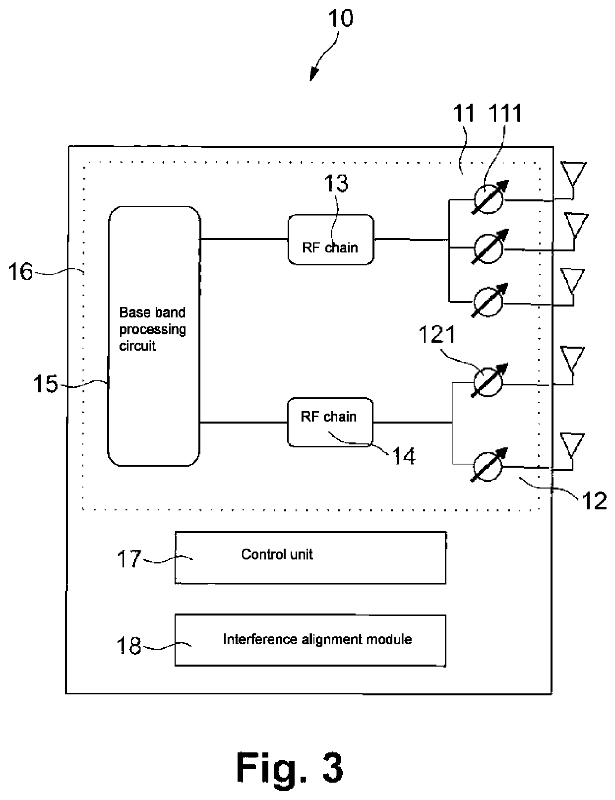
[0039]The function of the interference alignment module 18 is described in detail with reference to FIG. 4. FIG. 4 shows a simplified flow chart of the communication method for interference alignment according to the present disclosure. In particular, FIG. 4 shows the steps required to perform interference alignment according to the present disclosure. It is understood that the communication method may include further steps or additional intermediate steps which are not depicted in this flow chart.

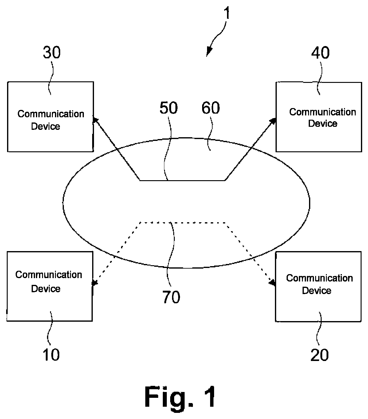
[0040]In FIG. 4, with reference numerals 301 and 302, a first and a second input to the interference alignment process are denoted. The first input 301 constitutes channel characteristics between the first communication device and one of the further communication devices. Preferably, the channel characteristics are an estimation of the channel between these two devices which is determined by the first communication device detecting flow control signals exchanged between the further communi...

embodiment 1

[0098]2. The first communication device , wherein the interference alignment module (18) is configured to obtain the channel characteristics and the non-reciprocity mismatch without requiring exact channel coefficients from each individual antenna element of the further communicating device.

[0099]3. The first communication device according to any one of embodiments 1 or 2, wherein the interference alignment module (18) is configured to determine the channel characteristics by detecting flow control signals that are exchanged over the link between the pair of further communication devices (30, 40).

[0100]4. The first communication device according to any one of embodiments 1 to 3, wherein the interference alignment module (18) is configured to apply one or more receive beamformers to determine the channel characteristics between a transmitting device of the pair of further communication devices (30, 40) and the first communication device (10).

[0101]5. The first communication device (1...

embodiment 7

[0104]8. The first communication device , wherein the mismatch information includes a level of non-reciprocity of the transmission and reception antenna patterns of the pair of further communication devices (30, 40).

[0105]9. The first communication device according to embodiment 7, wherein the mismatch information includes a value quantifying the mismatch between the transmission and reception antenna patterns of the at least one of the pair of further communication devices and information indicative of a distance measure based on which this value was calculated.

[0106]10. The first communication device according to any one of embodiments 7 to 9, wherein the mismatch information is included in flow control signals exchanged between the pair of further communication devices (30, 40).


PUM


Abstract

A first communication device for communicating with a second communication device over a link that is utilized at the substantially same time and with the substantially same frequency resource by a pair of further communication devices. The first communication device comprises one or more antenna arrays with which beamforming can be performed, a controller configured to apply beamformers to control beamforming by the one or more antenna arrays, and circuitry configured to determine whether at least one of the beamformers satisfies an interference condition such that a level of interference leaked to the further communication devices by the first communication device is below a defined threshold, and if available, select the at least one beamformer for communicating with the second communication device.

Description

CROSS-REFERENCE TO RELATED APPLICATIONS[0001]The present application is based on PCT filing PCT / EP2017 / 070474, filed Aug. 11, 2017 which claims priority to EP 16188126.3, filed Sep. 9, 2016, the entire contents of which are incorporated herein by reference.BACKGROUNDField of the Disclosure[0002]The present disclosure relates to a communication device and a communication method for communicating over a link that is utilized substantially at the same time and with the same frequency resources by a pair of further communication devices. Further, the present disclosure relates to an interference alignment module used in such communication device as well as to computer product for implementing the communication method.Description of Related Art[0003]The use of the millimeter (mm) wave band for wireless communication has gained considerable attention recently as vast amounts of spectrum are available in the mm-wave band (typically considered to be between 30 and 300 GHz) allowing high dat...

Claims


Application Information

Patent Timeline
Patent Type & Authority Patents(United States)
IPC IPC(8): H04B7/06H04B7/08H04W74/08
CPCH04B7/0695H04B7/06H04B7/0617H04B7/08H04B7/086H04W74/0816H04W16/14
Inventor CIOCHINA, DANAHANDTE, THOMASLOGHIN, NABIL SVENFELLHAUER, FELIX
Owner SONY CORP
Why Eureka
Try Eureka