Electrical connector

a technology of electrical connectors and connectors, applied in the direction of conduction heat transfer, coupling device connections, instruments, etc., can solve the problem of unpreferable cooling efficiency of electrical connectors, and achieve the effect of preventing the operation of connectors, enhancing the cooling efficiency of electrical connectors, and avoiding accumulation of hea

Active Publication Date: 2021-07-13
DONGGUAN LUXSHARE TECH CO LTD
View PDF20 Cites 7 Cited by
  • Summary
  • Abstract
  • Description
  • Claims
  • Application Information

AI Technical Summary

Benefits of technology

[0006]The embodiments of the present disclosure could enhance the cooling efficiency of the electrical connector by providing a heat pipe conducting the heat from the partition heat sink in the electrical connector housing to the outside, avoiding the accumulation of heat and preventing the operation of connectors from being affected by the rising temperature.

Problems solved by technology

The conventional heat sinks installed within the electrical connector could not effectively conduct the heat generated by the electrical connector to the outside, resulting in an unpreferable cooling efficiency for the electrical connector.

Method used


Image

  • Electrical connector
  • Electrical connector
  • Electrical connector

Examples


Embodiment Construction

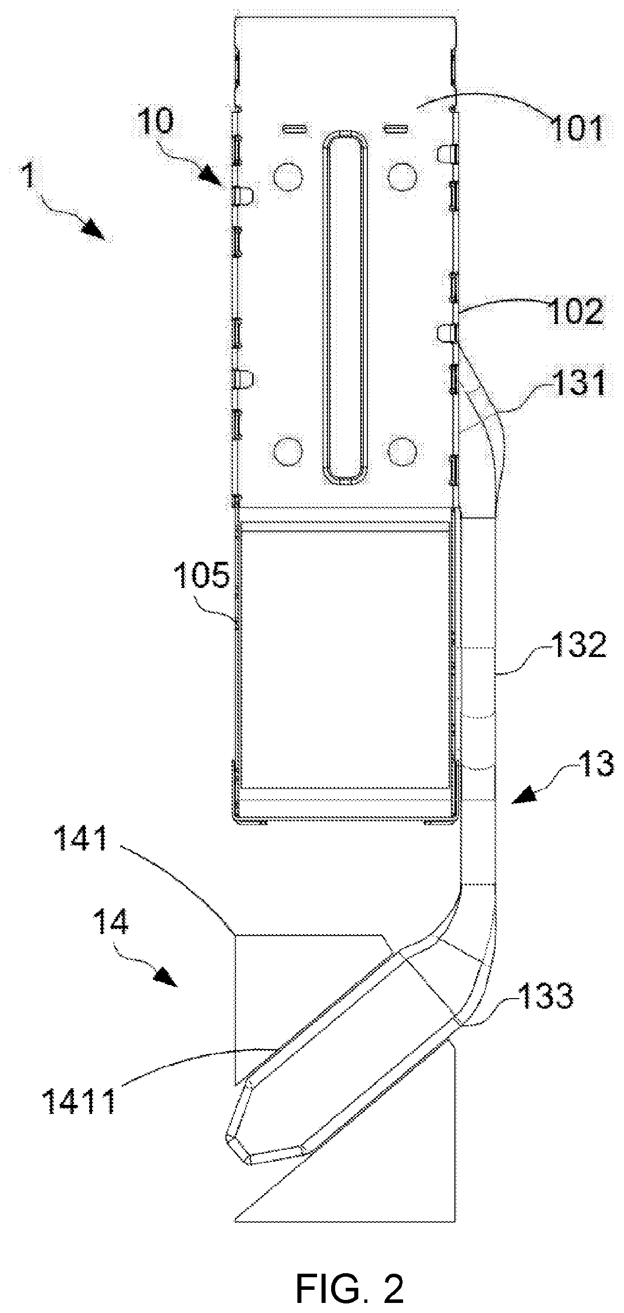
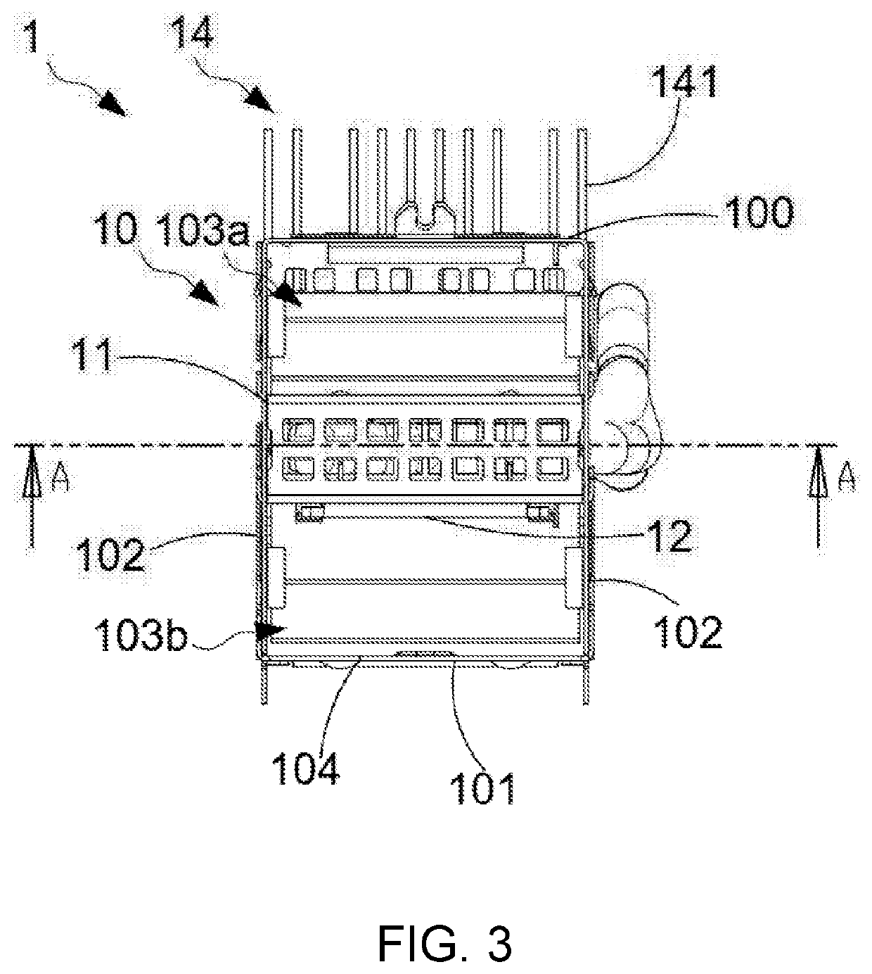
[0015]The present invention will now be described more fully hereinafter with reference to the accompanying drawings, in which exemplary embodiments of the invention are shown. This present invention may, however, be embodied in many different forms and should not be construed as limited to the embodiments set forth herein. Rather, these embodiments are provided so that this present invention will be thorough and complete, and will fully convey the scope of the present invention to those skilled in the art.

[0016]Certain terms are used throughout the description and following claims to refer to particular components. As one skilled in the art will appreciate, manufacturers may refer to a component by different names. This document does not intend to distinguish between components that differ in name but function. In the following description and in the claims, the terms “include / including” and “comprise / comprising” are used in an open-ended fashion, and thus should be interpreted as ...


PUM


Abstract

The present disclosure provides an electrical connector comprising an electrical connector housing, a partition part, a partition heat sink, a heat pipe, and a cooling module. The electrical connector housing comprised an upper surface, a lower surface, and two opposite sidewalls. The partition part is disposed in the electrical connector housing. The partition heat sink is disposed on the partition part and is disposed in the electrical connector housing. One end of the heat pipe is connected to the partition part. The cooling module is disposed at the outside the electrical connector housing and is connected to the other end of the heat pipe. The cooling efficiency is enhanced by conducting the heat of the partition heat sink to the outside of the electrical connector through a heat pipe to avoid heat accumulating in the electrical connector housing.

Description

CROSS REFERENCE TO RELATED APPLICATION[0001]This application claims the priority benefit of Chinese Patent Application Serial Number 201921669765.9, filed on Oct. 8, 2019, the full disclosure of which is incorporated herein by reference.BACKGROUNDTechnical Field[0002]The present disclosure relates to the technical field of electrical connector, and more particularly to an electrical connector.Related Art[0003]Electrical connectors are usually equipped with heat sinks, which conduct the heat generated during the operation of electrical connectors to the outside, avoiding the accumulation of heat and preventing the operation of connectors from being affected by the rising temperature. The conventional heat sinks installed within the electrical connector could not effectively conduct the heat generated by the electrical connector to the outside, resulting in an unpreferable cooling efficiency for the electrical connector.SUMMARY[0004]The embodiments of the present disclosure provide an...

Claims


Application Information

Patent Timeline
Patent Type & Authority Patents(United States)
IPC IPC(8): H05K7/20H01R13/518
CPCH05K7/2039H01R13/518H05K7/20336H05K7/20418H05K7/20436F28D15/0233F28D15/0275F28D2021/0029G02B6/4269
Inventor WANG, XIAOKAILUO, ZHENDUAN, BAIYUWU, XIAOPING
Owner DONGGUAN LUXSHARE TECH CO LTD
Why Eureka
Try Eureka