Quick drain, low mess, hydrostatic transmission filter and plug assembly

Active Publication Date: 2021-07-20
PARKER INTANGIBLES LLC
View PDF4 Cites 0 Cited by
  • Summary
  • Abstract
  • Description
  • Claims
  • Application Information

AI Technical Summary

Benefits of technology

The patent describes an improved filter component for hydrostatic transmissions. The component includes a cartridge for filtering fluid and a plug assembly with two plugs, one larger and one smaller. The smaller plug can be removed to drain the fluid quickly and more controllably, minimizing oil mess. The large plug has a connector for easy replacement. The component also has a housing with a seal seat and a threaded inner surface for easy installation. Overall, the invention provides a low mess, quick drain filter component for filtering fluid in a hydrostatic transmission.

Problems solved by technology

With conventional configurations, however, as the filter element is loosened from the housing, the internal space of the housing becomes substantially exposed through the large hole where the filter component extends into the housing.
As a result, hydraulic fluid spills out from the housing rapidly and in an uncontrolled manner, which is messy and inconvenient and time-consuming to clean up.

Method used


Image

  • Quick drain, low mess, hydrostatic transmission filter and plug assembly
  • Quick drain, low mess, hydrostatic transmission filter and plug assembly
  • Quick drain, low mess, hydrostatic transmission filter and plug assembly

Examples


Embodiment Construction

[0022]Embodiments of the present invention will now be described with reference to the drawings, wherein like reference numerals are used to refer to like elements throughout. It will be understood that the figures are not necessarily to scale.

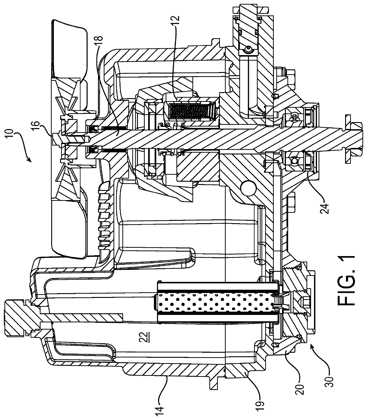
[0023]FIG. 1 is a drawing depicting a cross-sectional view of an exemplary hydrostatic transmission 10 with a filter component 30 in accordance with embodiments of the present invention. Although the filter component 30 is described in this disclosure in the context of such a hydrostatic transmission 10, it will be appreciated that the filter component is not limited to this example, but may be employed more generally in fluid systems in which fluid flows from a housing reservoir through a filter component located within the housing.

[0024]Referring to the example of FIG. 1, the hydrostatic transmission 10 includes a hydraulic pump assembly 12 enclosed or housed within a top housing 14, and a hydraulic motor assembly (not shown in this view). A...


PUM

PropertyMeasurementUnit
Diameteraaaaaaaaaa
Transmissionaaaaaaaaaa
Areaaaaaaaaaaa

Abstract

A filter component includes a cartridge portion including a filter media, and a plug assembly on which the cartridge portion is mounted and in fluid communication with the cartridge portion. The plug assembly comprises a first plug and a second plug, the first plug being larger than the second plug. The second plug is fixed to an inner surface of the first plug in an installed state and is removable from the first plug in a draining state. The first plug further defines a drain port, wherein in the installed state the second plug plugs the drain port and in a draining state the second plug is removed from the first plug to permit draining fluid through the drain port. The filter component may be incorporated into a hydrostatic transmission to permit controlled draining of fluid from the hydrostatic transmission that does not result in an oil mess.

Description

RELATED APPLICATIONS[0001]This application claims the benefit of U.S. Provisional Application No. 62 / 586,950 filed Nov. 16, 2017, which is incorporated herein by reference.FIELD OF INVENTION[0002]The present invention relates generally to filter assemblies used in transmission systems, and more particularly to filter assemblies for hydrostatic transmissions for use in light vehicles, such as turf mowing machines and zero-turn radius vehicles.BACKGROUND[0003]A prime mover, such as an internal combustion engine or the like, can be connected to a hydrostatic transmission to drive a wheel in a light vehicle. A hydrostatic transmission is particularly suitable to provide traction drive for light vehicles such as turf machines, lawn tractors, ride-on lawn mowers, and like devices. A hydrostatic transmission may be connected to a variety of gearboxes and transaxles, so the same components can be utilized on a wide variety of light vehicle models. A simple usage of hydrostatic transmissions...

Claims


Application Information

Patent Timeline
IPC IPC(8): B01D29/33B01D35/26B01D35/14F16H39/04
CPCB01D29/33B01D35/14B01D35/26F16H39/04B01D2201/291B01D2201/34B01D29/21B01D35/0276B01D35/16B01D2201/295
Inventor RICHARDSON, JASON SCOT
Owner PARKER INTANGIBLES LLC
Why Eureka
Try Eureka