Automatic drive belt biasing device

a technology of automatic drive and biasing device, which is applied in the direction of control devices, conveyor parts, roller-ways, etc., can solve the problems of wear and fatigue of the drive element, and achieve the effect of reducing the maintenance requirements of the conveyor system and reducing wear and fatigu

Active Publication Date: 2021-07-27
DEMATIC
View PDF10 Cites 0 Cited by
  • Summary
  • Abstract
  • Description
  • Claims
  • Application Information

AI Technical Summary

Benefits of technology

[0004]The present invention provides a live roller conveyor including an automatic drive element or drive member biasing device for adjusting the position and tension of a drive element to maintain adequate frictional contact between the drive element and rollers of a roller conveyor system. The automatic biasing device adjusts the position of the drive element by applying a biasing force to the drive element. The automatic biasing device includes a spring for automatically adjusting the biasing force as required due to factors including stretching of the drive element, rattling and shaking of the conveyor system, bouncing of the drive element, power surges from a drive motor experienced by the drive element, and other factors that will be appreciated. The automatic biasing device decreases wear and fatigue in the drive element due to inadequate tension and decreases maintenance requirements of the conveyor system, such as manually adjusting or tightening drive element tensioning or biasing devices.
[0006]In one aspect, the pivot arm of the automatic biasing device includes a long leg or member and a short leg or member fixed together at respective proximal ends to form the pivot arm. Preferably, the long leg and short leg are fixed at an obtuse angle with respect to each other. A pivot hole is disposed proximate to the intersection of the proximal ends of the long and short leg. Each of the long and short leg includes a guide wheel mount hole and a spring mount hole disposed in the pivot arm near their respective distal ends. Optionally, the long leg includes an indicator, such as a shape disposed on or in the long leg, such as a circle or triangle hole, and the short leg includes a different indicator, such as a different shape disposed on or in the short leg, such as a square hole. The indicators allow a user to easily identify which leg is the long leg and which leg is the short leg.
[0009]In one aspect, the opposing or scissoring pivot arms of the automatic biasing device include a long leg and a short leg fixed together at respective proximal ends to form each of the pivot arms. Preferably, the long leg and short leg are fixed at an obtuse angle with respect to each other. A pivot hole is disposed proximate to the intersection of the proximal ends of the long and short legs. A pair of the pivot arms are pivotably coupled together at the pivot holes of the pivot arms. Each of the long and short legs include a guide wheel mount hole and a spring mount hole disposed in the pivot arm near their respective distal ends. Optionally, the long legs include an indicator, such as a shape disposed on or in the long leg, such as a circle or triangle hole, and the short legs include a different indicator, such as a different shape disposed on or in the short leg, such as a square hole, such that a user may easily identify which legs are longer or shorter.
[0013]Therefore, the present invention provides a device and method for automatically biasing an endless drive element of a roller conveyor. The automatic belt biasing device includes a spring to automatically adjust the biasing force applied to the drive belt to maintain frictional contact between the drive belt and a roller or rollers of the conveyor. The automatic belt biasing device reduces wear of the drive belt by absorbing shock, vibration, and bouncing of the drive belt and may take up some slack caused by lengthening of the drive belt over time due to fatigue in the belt. The automatic belt biasing device may include adjustable guide wheel pitch distances or spacings such that the device can be disassembled or reconfigured from one wheel pitch configuration into a different wheel pitch configuration.

Problems solved by technology

The automatic biasing device decreases wear and fatigue in the drive element due to inadequate tension and decreases maintenance requirements of the conveyor system, such as manually adjusting or tightening drive element tensioning or biasing devices.

Method used


Image

  • Automatic drive belt biasing device
  • Automatic drive belt biasing device
  • Automatic drive belt biasing device

Examples


Embodiment Construction

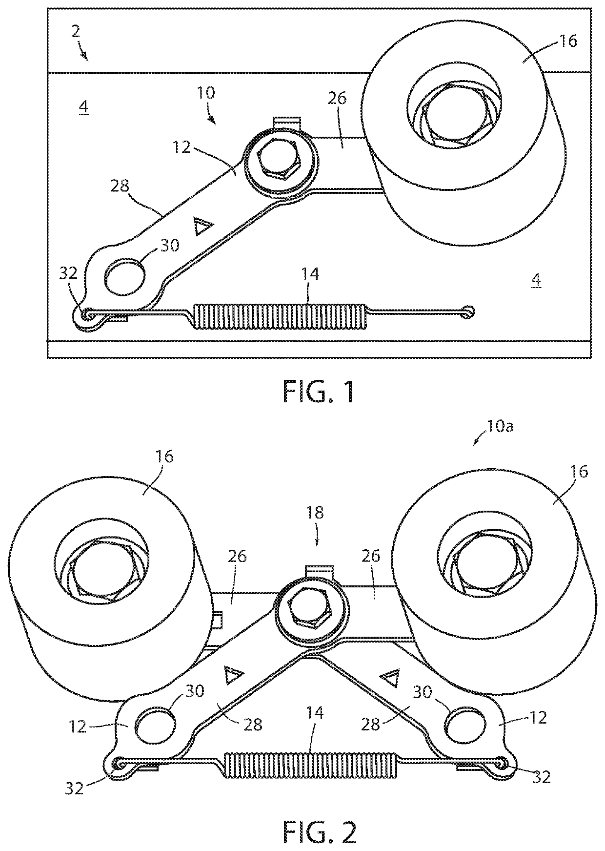
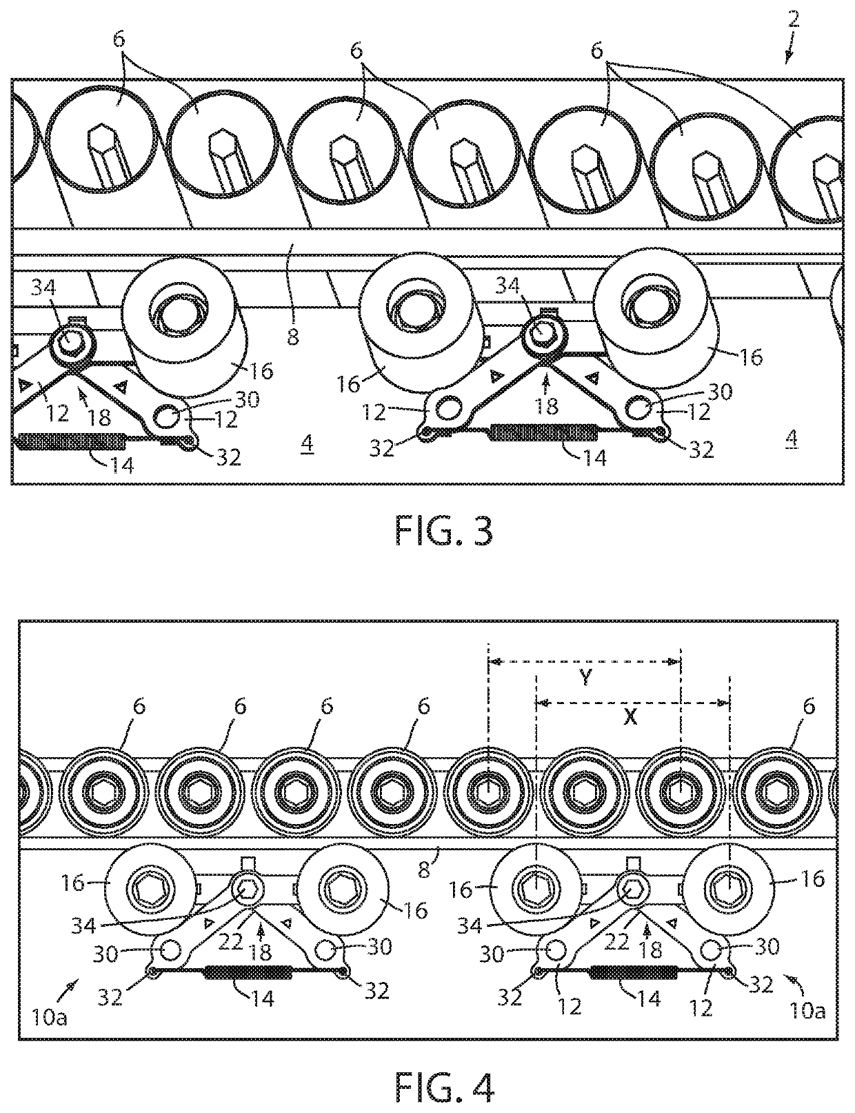
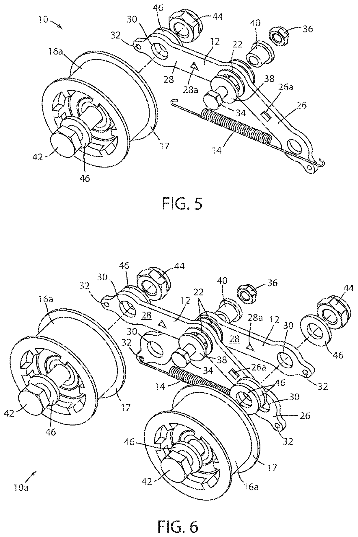
[0025]Referring now to the drawings and the illustrative embodiments depicted therein, a roller conveyer 2 includes a conveyor frame 4, a plurality of freely rotatable rollers 6 disposed along the conveyor frame 4, an endless drive element or member 8, and an automatic drive member biasing device 10. The endless drive member 8 may be a drive belt such as any of a v-belt, a poly v-belt, a flat belt, a flanged belt, a round belt, and a double v-belt. The automatic drive belt biasing device 10 includes a at least one pivoting arm, leg frame, or body 12, a spring 14, and at least one drive belt guide wheel 16 in combination, configured to bias the endless drive member 8 into frictional contact with at least one of the conveyor rollers 6 (FIG. 1). The spring 14 is coupled to a portion of the pivot arm 12 to bias the guide wheel 16 toward the drive member 8. The spring 14 is preferably a tension spring, however, it will be appreciated that the automatic biasing device 10 may utilize other...


PUM


Abstract

An automatic belt biasing device is provided for biasing a drive belt into frictional contact with rollers of a conveyor. The belt biasing device maintains a drive belt in contact with rollers of a live roller conveyor to provide drive for the rollers to propel items or packages along the conveyor. A spring attached to a pivot arm or pair of scissoring pivot arms adjusts a biasing force applied by guide wheels of the belt biasing device to the drive belt due to changes in drive belt tension. The belt biasing device may be selectively adjustable based on required roller pitch distances. The belt biasing device is pivotably coupled to the roller conveyor allowing the guide wheels to apply equal pressure to the drive belt while allowing the pivot arms to actuate and increase or decrease the biasing force provided by the belt biasing device.

Description

CROSS REFERENCE TO RELATED APPLICATION[0001]The present application claims priority of U.S. provisional application Ser. No. 62 / 846,205 filed May 10, 2019, which is hereby incorporated herein by reference in its entirety.FIELD OF THE INVENTION[0002]The present invention is directed generally to powered conveyors and, more particularly, to powered roller conveyors.BACKGROUND OF THE INVENTION[0003]Roller transport conveyors are known to include a plurality of rollers for conveying objects such as packages thereon. The rollers may be powered by a drive device such as an endless drive belt that is driven by an electric motor or the like. Manually adjustable belt tensioners or biasing devices are often provided with a roller transport conveyor to adjust the position of a belt to bias the belt into frictional contact with the rollers to drive the rollers and the conveyor. Improper drive belt tension, either too much or too little tension, due to improper belt positioning increases wear on...

Claims


Application Information

Patent Timeline
Patent Type & Authority Patents(United States)
IPC IPC(8): B65G23/44B65G43/00B65G13/07
CPCB65G23/44B65G13/07B65G43/00B65G13/071B65G23/12
Inventor DUNCAN, JEFFERY D.THOMAS, NICHOLAS M.PILARZ, NOLAN R.TRIESENBERG, THOMAS H.HEBBUR, SHREEDHAR M.
Owner DEMATIC
Why Eureka
Try Eureka