
Cross-platform universal tire pressure monitoring sensor

a technology of tire pressure monitoring and sensor, which is applied in the direction of tire measurement, measurement devices, instruments, etc., can solve the problems of high initial investment of installers and supply, time-consuming sensor selection, and inability to use a multitude of sensor types, etc., and achieves low cost, simple handling, and large flexibility.

Active Publication Date: 2021-07-27
WEGMANN AUTOMOTIVE GMBH
View PDF15 Cites 0 Cited by
  • Summary
  • Abstract
  • Description
  • Claims
  • Application Information

AI Technical Summary

Benefits of technology

[0013]The embodiments are based on the object of providing a universal TPMS wheel sensor (which may include not only the sensing element but also an appropriate electronic circuitry), which can be manufactured for low costs, allows simple handling and provides large flexibility. More specifically, modifying the hardware components of the sensor (including the processing unit) should not affect in any way any other party involved in the sensor after-market (installers, programming tool producers, salesmen, etc.) and it does not require any distinction between old and new hardware versions. The sensor should be adaptable to a large number of vehicles using different TPMS implementations. The sensor memory requirements should be small. The sensor should be future proof and adaptable to new communication protocols. The programming time during sensor installation should be comparatively short. A programming cable of the wire programming interface preferably is not required.
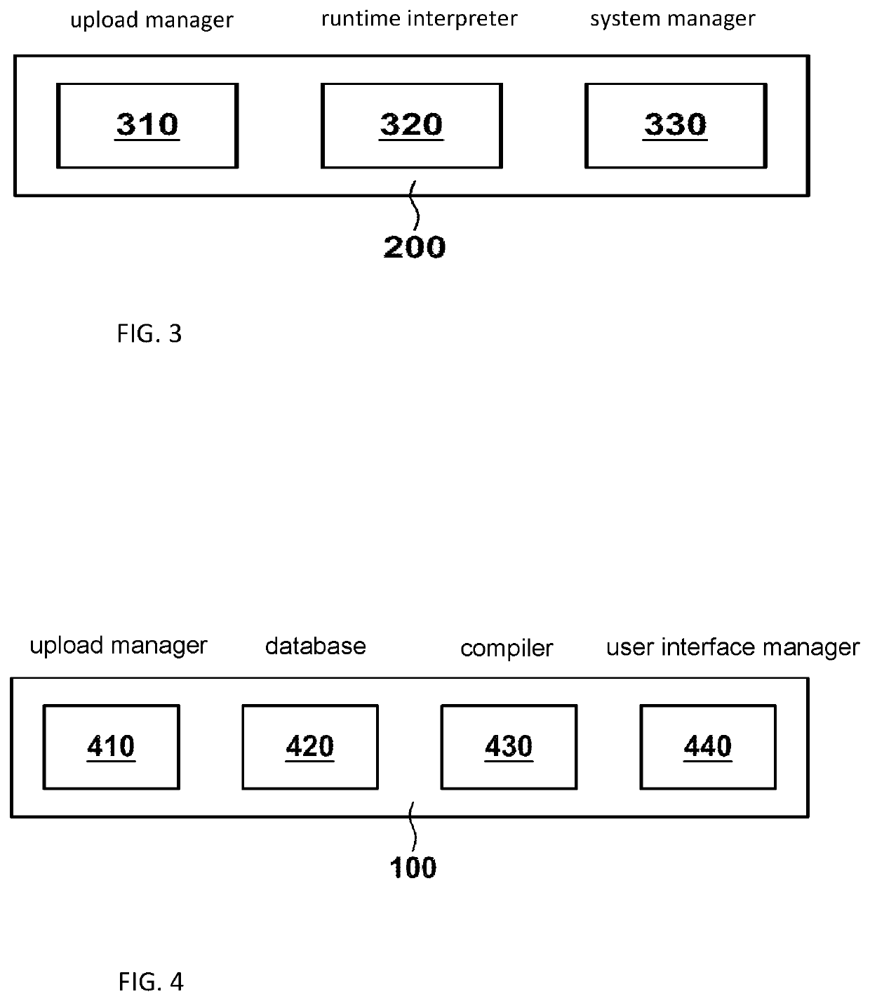
[0016]The sensor contains an implementation of a Virtual Machine, comprising a runtime interpreter, which interprets the IL program in runtime. The IL implementation of the state machines can be stored in the memory during production, and / or it can be loaded in post-issuance by the sensor installer using a dedicated tool. The IL is preferably generated by a compilation of the DSL. Preferably the DSL is a high level language which can easily be handled by humans. For example it may be a graphical or declarative language. The IL is a lowest level language, which may be a byte code and which is directly interpreted by the runtime interpreter in the sensor. There may be any intermediate stages between the DSL and the IL at a lower level which is less readable, but allows for more detailed and optimal implementation. As the IL program is significantly shorter than the full program (as in US 2014 / 0165026 A1), program loading time to a sensor is reduced significantly. By the IL, the implementation is hardware independent and may be used on different sensor hardware, for example comprising a different processing unit. This allows for a significant flexibility. A DSL developed once may be re-used for different sensor hardware configurations. Also, a hardware modification does not require any software modification. The interpreter design may also permit executing the DSL program directly, thus eliminating the need to compile it to its IL representation. This is not a preferred solution, however, as it would compromise the program readability or memory footprint.

Problems solved by technology

Understandably, using a multitude of sensor types is not desirable, as it requires the sensor installers to have a multitude of TPMS sensors on stock.
This results in a high initial investment for the installer and the supply chain and makes the sensor selection time consuming.
Furthermore, the intense communication would reduce the capacity of the battery built into the sensor.
Such a wired interface requires additional hardware like drivers and electrical contacts, which make the sensor susceptible to ESD damage and corrosion at the electrical contact points.
The handling of a wired interface is more complex as a cable has to be connected to the sensor prior to programming and disconnected after programming.
The drawback of this solution is that a large number of programs have to be stored in the sensor which further requires a large overhead of memory, increasing the sensors costs.
A further disadvantage is that, due to pre-stored programs, no adaption to future requirements is possible.
As initially a large number of encoding procedures has to be stored in memory, a comparatively large memory is required or the memory limitation of commercial micro-controllers forces a number of sensors to be stocked which further increases the costs of the sensor.
Finally, adaption to new cars is not always possible, unless they fit into an existing scheme.
For that reason the modification of a sensor hardware platform requires introduction of new version number of the sensor, which immediately affects other parties involved in the sensor after market.
In other words, the operation of each of the involved party becomes more involved and complex.
Accordingly, sensor versioning results in extra costs, greater handling complexity, time slips and return rates.
It is well recognized in the art that such drawbacks discourage the TPMS sensor producers from modifying the hardware platform of the sensors at the pace of technological advances, which leads to low dynamics of the sensor market, greater costs of the sensors, and lower functional and user safety.
None of the above-mentioned prior art references addresses this problem directly.
This is not a preferred solution, however, as it would compromise the program readability or memory footprint.

Method used


Image

  • Cross-platform universal tire pressure monitoring sensor
  • Cross-platform universal tire pressure monitoring sensor
  • Cross-platform universal tire pressure monitoring sensor

Examples


Embodiment Construction

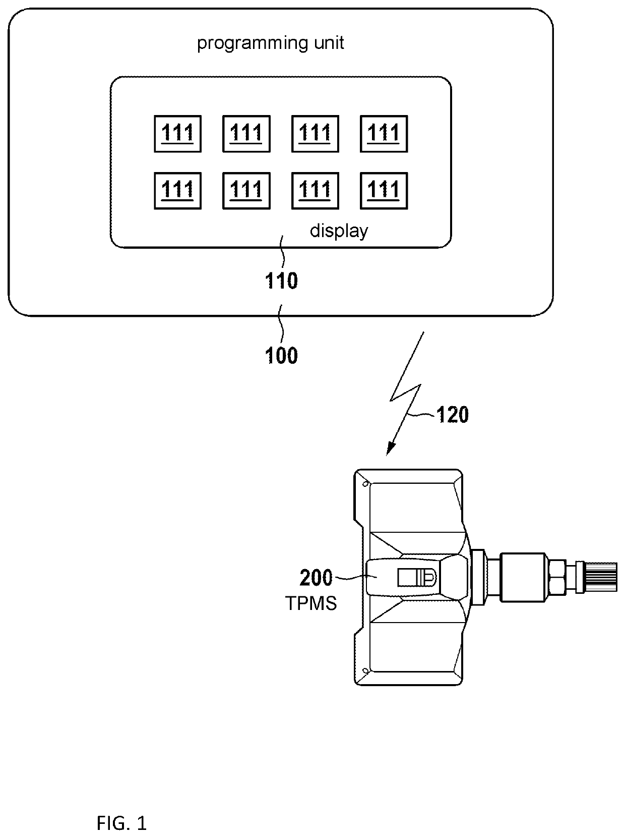
[0031]In FIG. 1, an embodiment of a basic TPMS programming system is shown. A programming unit 100 may have a display 110, which preferably is configured as a touch screen display. The display 110 may provide the user a plurality of options, for example for selecting different car manufacturers, models and years. The programming unit will select the appropriate code for a TPMS sensor and upload it, for example via a wireless communication interface 120, to a TPMS sensor 200.

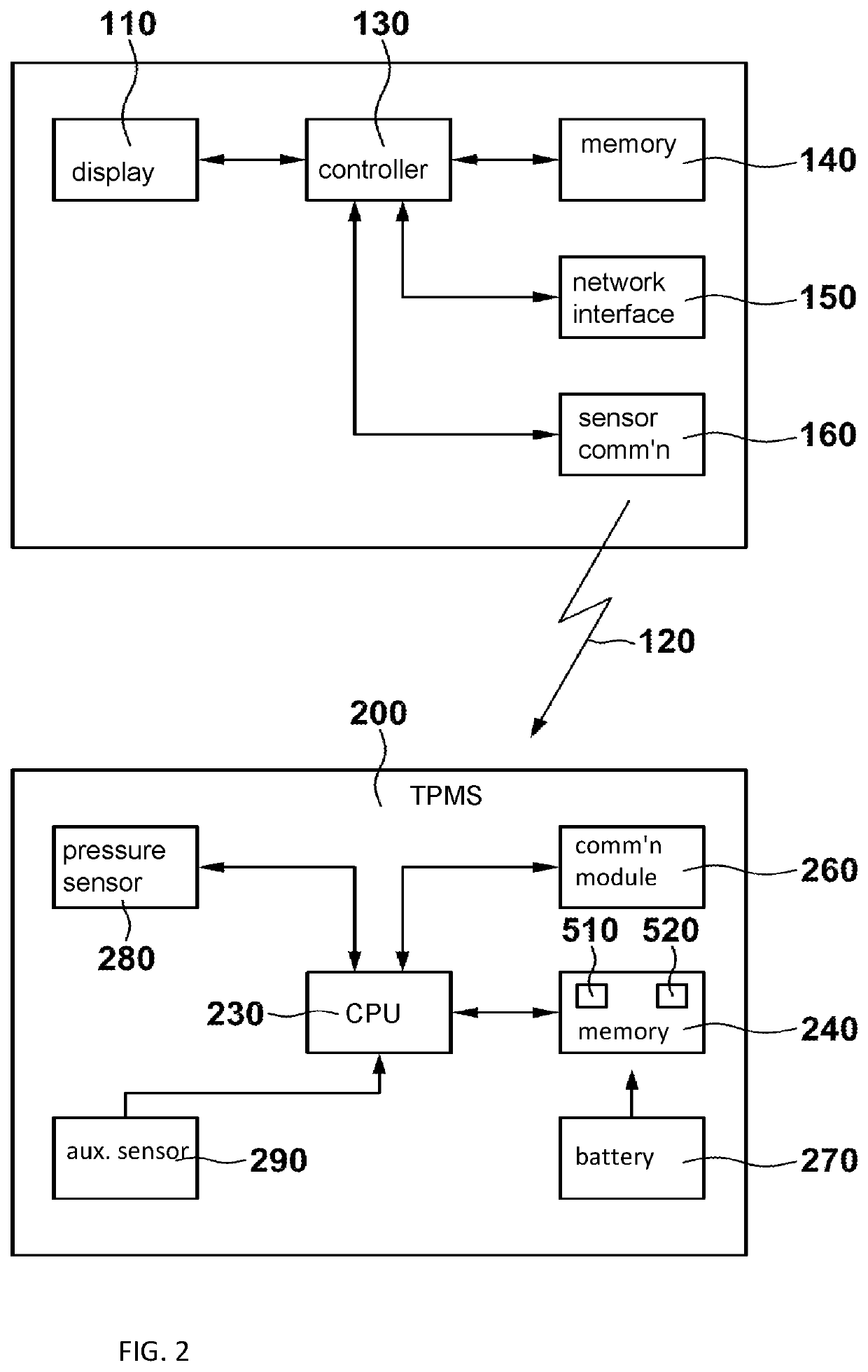
[0032]In FIG. 2, more details of a TPMS sensor programming system are shown. The programming unit 100 preferably has a microcontroller or microprocessor 130, which is further connected to a non-transitory tangible memory or a storage 140. The memory storage 140 may be organized as a database and may contain information or data about or representing vehicles and TPMS sensors. The memory storage 140 may be implemented in various configurations such as, for example, any kind of RAM / ROM, a disk drive, or a network-co...


PUM

PropertyMeasurementUnit
pressureaaaaaaaaaa
timeaaaaaaaaaa
pressureaaaaaaaaaa

Abstract

A tire pressure monitoring sensor comprises an environmental pressure sensor, a non-volatile memory for storing a first program and a second program, a processing unit for executing the first program, a communication module including a wireless transmitter for transmitting at least one parameter indicative of conditions within a tire and a wireless or wired receiver for loading the second program into the non-volatile memory and a battery for powering the sensor. The second program contains a sensor operation description which is used by the first program.

Description

CROSS-REFERENCE TO RELATED APPLICATIONS[0001]This application is a continuation in part from the pending U.S. patent application Ser. No. 15 / 370,891 published as US 2017 / 0158000A1, which claims priority from the European Application No. 15198266.7 filed on Dec. 7, 2015. The disclosure of each of the above-identified patent applications is incorporated by reference herein.BACKGROUND1. Field of the Invention[0002]The invention relates to tire pressure monitoring sensors for vehicles and specifically to universal tire pressure monitoring sensors which are adaptable to a variety of vehicles and a variety of sensor hardware platforms.2. Description of Related Art[0003]A tire-pressure monitoring system (TPMS) is an electronic system for monitoring the air pressure inside a pneumatic tire on various types of vehicles. A TPMS reports in near real-time tire-pressure information to the vehicle's control system and to the driver. The TPMS mentioned herein are direct TPMS, which are mounted ins...

Claims


Application Information

Patent Timeline
Patent Type & Authority Patents(United States)
IPC IPC(8): G01L19/08B60C23/04B60C23/00
CPCG01L19/086B60C23/0471B60C23/001
Inventor WICHER, BARTLOMIEJRIEMANN, ANDREAS
Owner WEGMANN AUTOMOTIVE GMBH
Learn More