Network system and management method and apparatus thereof

a network system and management method technology, applied in the field of network systems, can solve problems such as significant costs, and achieve the effect of faster and more efficient network services

Active Publication Date: 2021-08-03
NEC CORP
View PDF7 Cites 0 Cited by
  • Summary
  • Abstract
  • Description
  • Claims
  • Application Information

AI Technical Summary

Benefits of technology

[0016]As described above, according to the present invention, it is possible to provide the increased number of options about a communication path comprised of processing units on which VNFs operate, allowing suitable selection of a communication path to make network services faster and more efficient.

Problems solved by technology

For this reason, when launching a new network service, the network operator is forced to introduce a new dedicated hardware device, requiring significant costs for purchasing appliances, installation spaces, and the like.

Method used


Image

  • Network system and management method and apparatus thereof
  • Network system and management method and apparatus thereof
  • Network system and management method and apparatus thereof

Examples


embodiment

1. EMBODIMENT

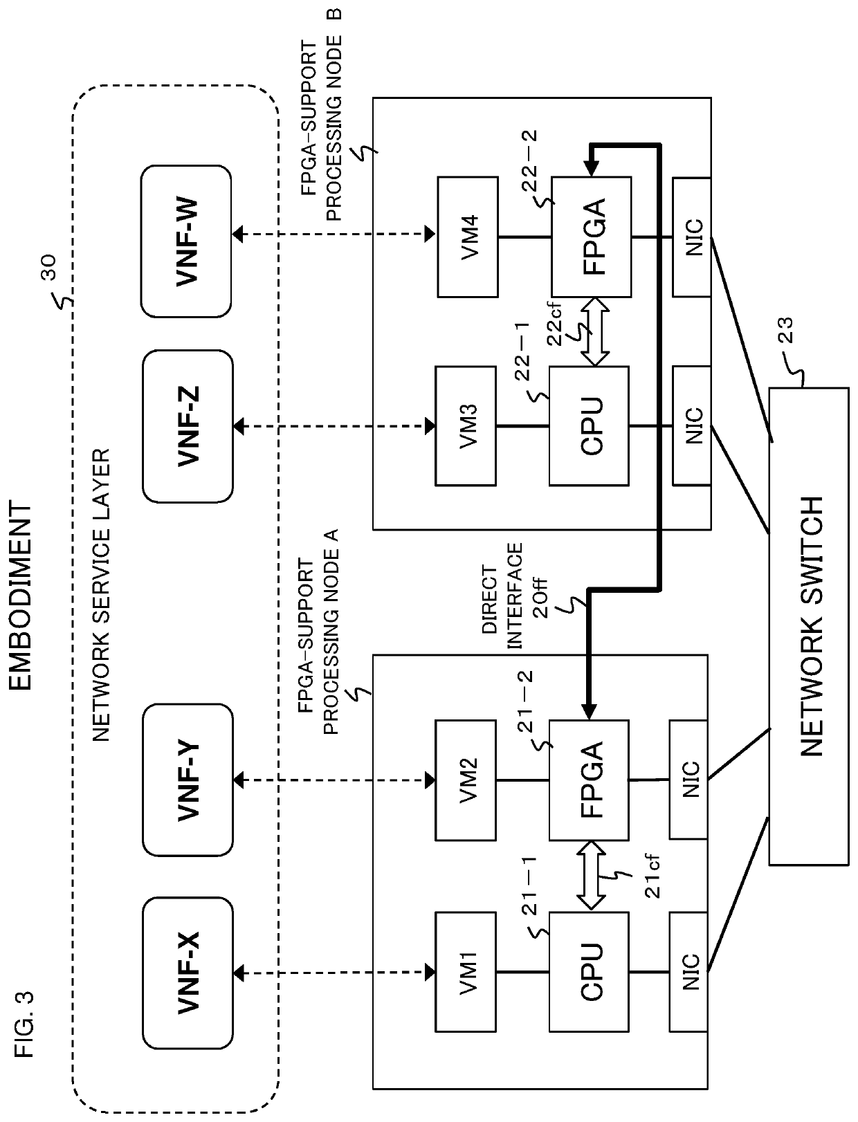
[0038]In a network system according to an embodiment of the present invention, in addition to a communication interface between processing nodes through a network, the following communication interfaces are used: a communication interface between the CPU and the FPGA of a FPGA-support processing node; and a direct communication interface with the FPGA of another FPGA-support processing node, allowing a high-speed communication path without passing through the network or a network switch to be selected, and a desired forwarding graph can be implemented using the high-speed communication path. The present embodiment will be described below with reference to FIGS. 3 to 6.

1.1 System Configuration

[0039]As shown in FIG. 3, an FPGA-support processing node A in the lower-layer network 20 has a configuration in which a CPU 21-1 and an FPGA 21-2 are coupled with each other. In FIG. 3, it is assumed that a virtual machine VM1 is created on the CPU 21-1, a virtual machine VM2 is cr...

example 1

[0048]As illustrated in FIG. 5, a VNF image selection function 201 of the management apparatus 10 selects an efficient communication path that implements a desired forwarding graph, from the above VNF images. For example, if the forwarding graph includes the VNF-X, VNF-Y, and VNF-Z, the VNF image selection function 201 selects the VNF image CX2 of the CPU 21-1 and the VNF image FY5 of the FPGA 21-2 in the FPGA-support processing node A and a VNF image CZ1 of the CPU 22-1 in the FPGA-support processing node B. Then, the VNF image selection function 201 connects the CPU 21-1 and FPGA 21-2 through the CPU-FPGA interface and connects the FPGA 21-2 and the CPU 22-1 of the FPGA-support processing node B through the network switch. Thus, a communication path that implements the forwarding graph VNF (X-Y-Z) can be formed. Since this communication path uses the high-speed CPU-FPGA interface, the communication path can enhance the speed of communication, compared to typical communication thro...

example 2

[0049]As illustrated in FIG. 6, assuming that the forwarding graph is composed of a set of the VNF-X, VNF-Y, and VNF-W, the VNF image selection function 201 selects the VNF image CX2 of the CPU 21-1 and the VNF image FY4 of the FPGA 21-2 in the FPGA-support processing node A and a VNF image FW3 of the FPGA 22-2 in the FPGA-support processing node B. Then, the VNF image selection function 201 connects the CPU 21-1 and FPGA 21-2 through the CPU-FPGA interface and connects the FPGA 21-2 and the FPGA 22-2 through the fast interface 20ff. Thus, a communication path that implements the forwarding graph VNF (X-Y-W) can be formed. Since this communication path uses the high-speed CPU-FPGA interface and the high-speed FPGA-to-FPGA interface, the communication path can further enhance the speed of communication, compared to typical communication through the network switch.


PUM


Abstract

A network system includes multiple processing units (21-1, 21-2, 22-1, 22-2) on each of which a desired virtual network function can be configured and a management apparatus that determines a communication path that connects the processing units so as to deploy a set of desired virtual network functions. At least one of the processing units includes a first communication interface that is connectable to any different processing unit and at least one second communication interface that is directly connectable to a predetermined different processing unit. The management apparatus determines the communication path for deploying the set of the desire virtual network functions, in accordance with respective connectable communication interfaces of the processing units.

Description

CROSS REFERENCE TO RELATED APPLICATIONS[0001]This application is a National Stage of International Application No. PCT / JP2017 / 012224, filed on Mar. 27, 2017, which claims priority from Japanese Patent Application No. 2016-070564, filed on Mar. 31, 2016, the contents of all of which are incorporated herein by reference in their entirety.TECHNICAL FIELD[0002]The present invention relates to a network system including virtual network functions and, in particular to management techniques of the network system.BACKGROUND ART[0003]In current communication systems, various network functions (NFs), such as a broadband remote access server (BRAS), network address translation (NAT), a router, a firewall (FW), and deep packet inspection (DPI) are implemented by dedicated hardware devices (appliances). For this reason, when launching a new network service, the network operator is forced to introduce a new dedicated hardware device, requiring significant costs for purchasing appliances, installa...

Claims


Application Information

Patent Timeline
Patent Type & Authority Patents(United States)
IPC IPC(8): H04L12/24G06F9/455H04L45/42
CPCH04L41/0893G06F9/45558H04L41/0806H04L41/12H04L41/5041H04L41/5054G06F2009/45595H04L41/5077H04L41/40
Inventor SHIBATA, SEIYATAKENAKA, TAKASHIHASEGAWA, HIDEOISHII, SATORUNAKANO, SHINTARO
Owner NEC CORP
Why Eureka
Try Eureka