Remote PBX System and Advance Communication Terminals

a communication terminal and remote pbx technology, applied in the field of remote pbx system and advance communication terminals, can solve the problems of reducing so as to increase the cost of the communication operating system a small amount, improve the service life of the customer service provider, and improve the effect of customer service provider revenu

Inactive Publication Date: 2014-07-10
AUTOMATED BUSINESS
View PDF3 Cites 0 Cited by
  • Summary
  • Abstract
  • Description
  • Claims
  • Application Information

AI Technical Summary

Benefits of technology

[0020]In a preferred embodiment, the remote PBX service allows multiple-customer terminal numbers to be assigned to a single- or multiple-customer terminal at various physical locations and automatically manages the customer terminals for the customer in a manner that allows the customer to know which line has been called prior to answering the terminal. In this embodiment, the customer can decide to answer the called line at another location based on the Caller ID or other considerations, such as letting the phone be answered by those at the location where the line is connected.
[0021]The customer can remotely modify where the line numbers are directed to ring and appear in a manner similar to that now used to accomplish call forwarding. Existing phones or other terminal units used with the RPS require only a display and a simple Called Terminal ID (CTID) detection and transmission program to be implemented to convert the unit into an Advanced Communication Terminal (ACT) device. Once the terminals are modified to detect and display the CTID, the existing call forwarding service can be expanded to provide this additional service without having to provide a full RPS service. Billing can be done on a per-use or flat monthly service charge depending on the type of phone service provided by the RPS. In addition the RPS will allow various lines to be selected by the customer for making outgoing calls so that recipients having CID will detect the proper phone number as established by the customer in their various businesses or assigned to a family member.
[0022]By way of example, a customer that has the RPS service can dial a number such as *82 (or go to the RPS service provider's website) that then allows the customer to input a phone number from a list of approved predetermined numbers belonging to the customer, such as the customer's office, home and/or mobile numbers, to ring on the terminal being used to dial *82 (or the terminal specified at the RPS service provider's website) and the RPS will send the specified CTID when the number is ...

Problems solved by technology

However, the multiple lines associated with the legacy PBX still require multiple lines to be pulled to the customer location (either separate lines or a multiple-line trunk, such as a T1 line) where an LPS must be installed to distribute the lines to various local terminals.
In the case of mobile phones, such services as roaming, and the ability to have several numbers associated with the same mobile phone, are also available with limited success.
However, the customer must set the phone to one of the three numbers they want to use, which defeats the whole purpose of having three active lines.
Also, actual experience with this approach has not been successful because the numbers are tied to the terminal ESN and cloning detection software programs have made the phones inoperable in many cases.
However, this service will not automatically tell the user who is calling or tell them which line is being called.
However, these terminals have not been modified to detect and display inbound PBX information about the line being called, for example.
One problem to be solved is that of allowing a person to have several lines allocated to service several business or personal needs and letting the owner direct the incoming traffic to the terminal the owner specifies in a manner that lets the owner know which of the various lines is being called (as well as the calling party) prior to answering the terminal.
A related problem is that of allowing a user to h...

Method used


Image

  • Remote PBX System and Advance Communication Terminals
  • Remote PBX System and Advance Communication Terminals
  • Remote PBX System and Advance Communication Terminals

Examples


Embodiment Construction

1. Definitions

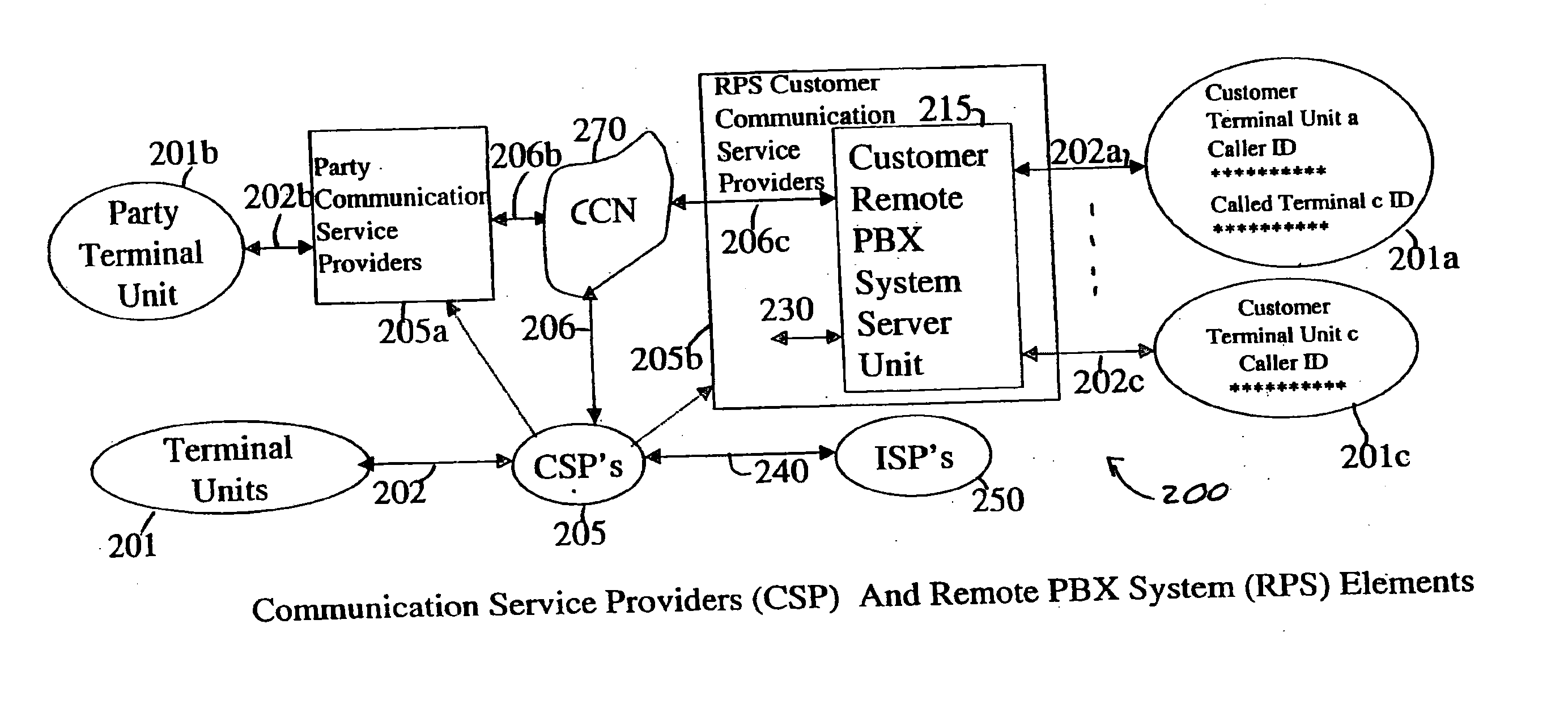
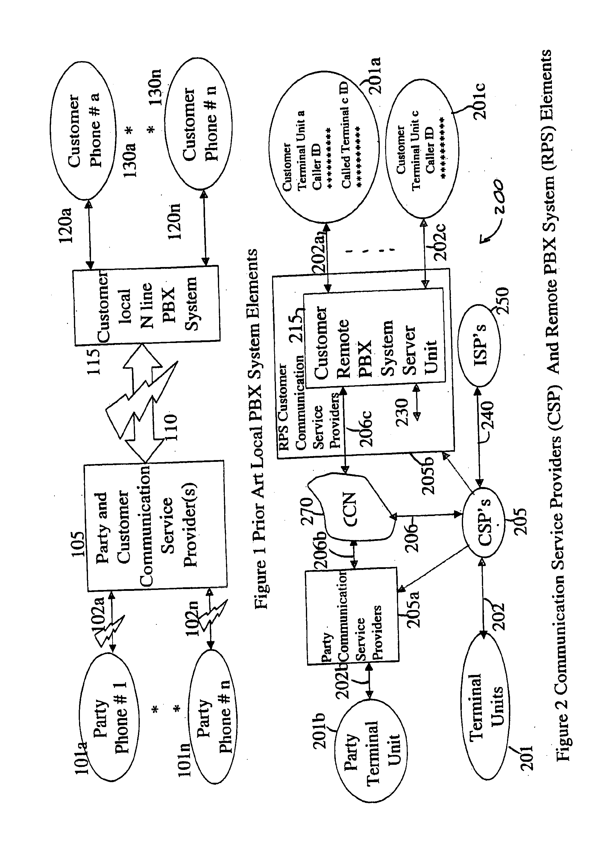
[0030]A “Local Private Branch Exchange System” is abbreviated throughout as “LPS”. The LPS is often referred to simply as a “PBX” in industry and business communities and the major elements of an LPS are shown in FIG. 1. However, since this invention “splits” the “PBX” tasks between a customer local system and a remote computer system, it is important to define the local “PBX” prior art system and services more precisely as an LPS for purposes of clarity. LPS are privately owned (or leased) computer and terminal units and connect to multiple communication lines provided normally by public communication service providers. The LPS is located, for example, at a company office or buildings owned by the company or institution such as a school or government agency. Small LPSs are also available for two- to ten-line service at homes and small businesses. The LPS directs both the incoming connections from the communication service provider and the outgoing connections to the c...


PUM


Abstract

A method for providing a remote PBX service by a customer's phone service provider. More than one telephone number is assigned to one customer's telephone communication link in communication with at least one telephone. A connect signal is received by the customer's phone service provider including one of the telephone numbers assigned to the customer's telephone communication link. A called telephone code is generated indicative of the number included in the connect signal. The called telephone code is sent to the customer's telephone communication link whereby a user of the customer's telephone communication link is capable of knowing which of the more than one telephone numbers assigned to the customer's telephone communication link was called prior to answering the telephone connected to the customer's telephone communication link. Thus, the customer's phone service provider provides the remote PBX service for the customer without the necessity of a local PBX.

Description

CROSS REFERENCE TO RELATED APPLICATIONS[0001]This application is a continuation of U.S. Ser. No. 11 / 787,070, filed Apr. 13, 2007 which is a continuation of U.S. Ser. No. 10 / 341,901, filed Jan. 13, 2003, which claims the benefit of U.S. Ser. No. 60 / 350,444, filed on Jan. 11, 2002; and to the provisional patent application U.S. Ser. No. 60 / 366,020, filed on Mar. 19, 2002, all of which are hereby incorporated herein by reference in their entirely.STATEMENT REGARDING FEDERALLY SPONSORED RESEARCH AND DEVELOPMENT[0002]Not Applicable.BACKGROUND OF THE INVENTION[0003]1. Field of the Invention[0004]The systems and devices relate to telecommunications, computers and communication terminal devices and central digital switches. In particular, it relates to local PBX and computer systems and to those related terminals associated with both PBX systems and to communication service provider services including, but not limited to call forwarding, call waiting, caller identification, voice box, short...

Claims


Application Information

Patent Timeline
IPC IPC(8): H04W84/16
CPCH04W84/16H04W40/02H04W76/11H04W76/10
Inventor FREENY, JR., CHARLES C.FREENY, III, CHARLES C.
Owner AUTOMATED BUSINESS
Why Eureka
Try Eureka