
Systems and processes for improved drag reduction estimation and measurement

a technology of estimation and measurement, applied in the direction of fluid removal, direct flow property measurement, borehole/well accessories, etc., can solve the problems of large stationary equipment, inability to accurately predict drag reduction on a larger scale, and typical field conditions that are not easily produced in a laboratory or small-scale flow loop, etc., to achieve accurate prediction of drag reduction, reliable prediction or estimation, and easy production

Active Publication Date: 2021-08-10
CHEVROU USA INC
View PDF57 Cites 0 Cited by
  • Summary
  • Abstract
  • Description
  • Claims
  • Application Information

AI Technical Summary

Benefits of technology

[0003]Unfortunately, current testing procedures of drag reducing properties of various agents requires large stationary equipment. Moreover, testing results are performed in the laboratory or small-scale flow loop and do not accurately predict drag reduction on a larger scale such as in the field. In particular, typical field conditions are not easily producible in a laboratory or small-scale flow loop. Accordingly, what is needed are systems and methods that more reliably predict or estimate drag reduction on a larger scale in the field. It would further be advantageous if testing systems could be made to be portable for small scale testing in the field. Advantageously, the instant inventions meet those needs and may have additional advantages that can lead to, for example, improved oil and / or gas production, better control of fracturing, and improved well design.

Problems solved by technology

Unfortunately, current testing procedures of drag reducing properties of various agents requires large stationary equipment.
Moreover, testing results are performed in the laboratory or small-scale flow loop and do not accurately predict drag reduction on a larger scale such as in the field.
In particular, typical field conditions are not easily producible in a laboratory or small-scale flow loop.

Method used


Image

  • Systems and processes for improved drag reduction estimation and measurement
  • Systems and processes for improved drag reduction estimation and measurement
  • Systems and processes for improved drag reduction estimation and measurement

Examples


specific embodiments

[0065]While the aforementioned upscaling processes for drag reduction agents may be accomplished in a number of ways, the specifics of a representative process are described below.

[0066]One may first make a solution with a specific concentration of drag reduction agents. Such a solution may be brine with any salinity and may include other chemicals such as surfactants, scale inhibitors, biocide, corrosion inhibitors. One then measures viscosity versus shear rate on the solution using, for example, a rheometer. This can be plotted as viscosity (e.g., units in centipoise: cP) on the Y-axis versus shear rate (e.g., units in reciprocal seconds: 1 / sec) on the X-axis.

[0067]FIG. 4 shows an example of a viscosity versus shear rate plot. In FIG. 4, measurements were taken at room temperature using a double-wall couette style rheometer. The sample contains a concentration of one gallon of drag reducing agent per 1000 gallons of tap water (i.e., 1 gpt). The circles represent the measured point...


PUM

PropertyMeasurementUnit
diameteraaaaaaaaaa
diameteraaaaaaaaaa
diameteraaaaaaaaaa

Abstract

The present invention relates generally to systems and processes for improved drag reduction estimation and measurement and more specifically to portable drag reduction analyzers and processes for upscaling drag reduction data for a variety of field applications. A drag reduction parameter AB for the fluid mixture is used for determining drag reduction for a fluid mixture in an oil field or pipeline operation.

Description

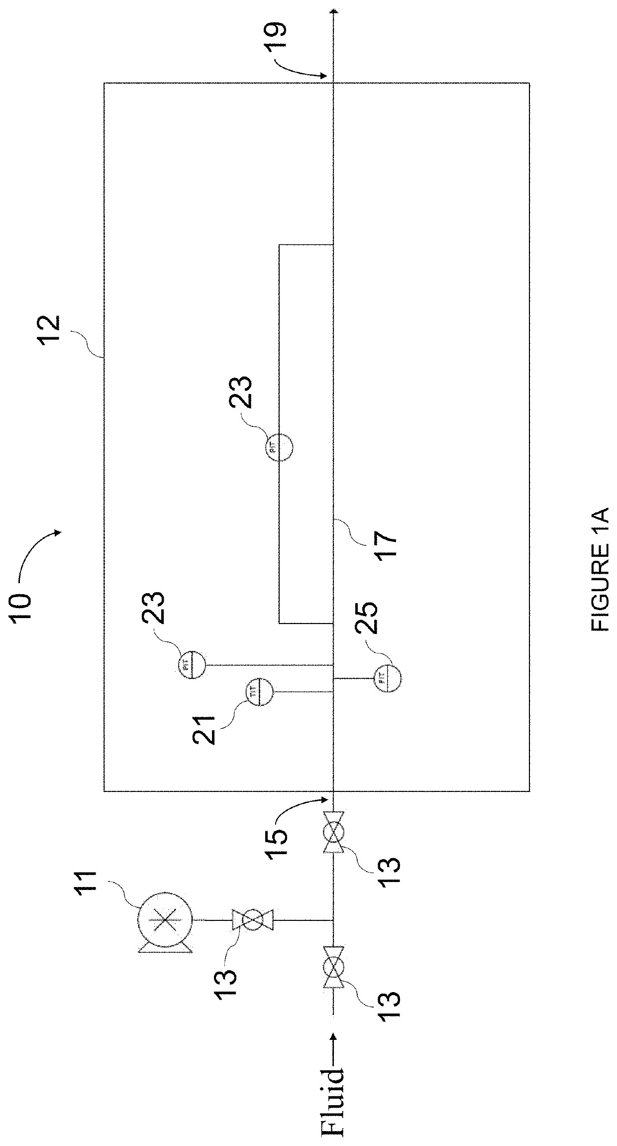
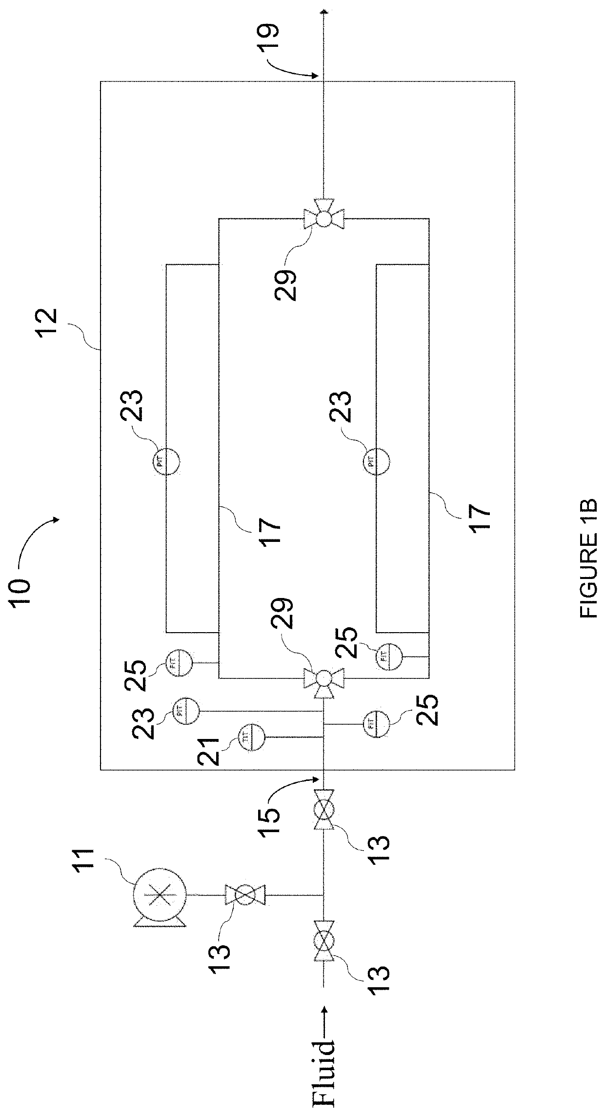
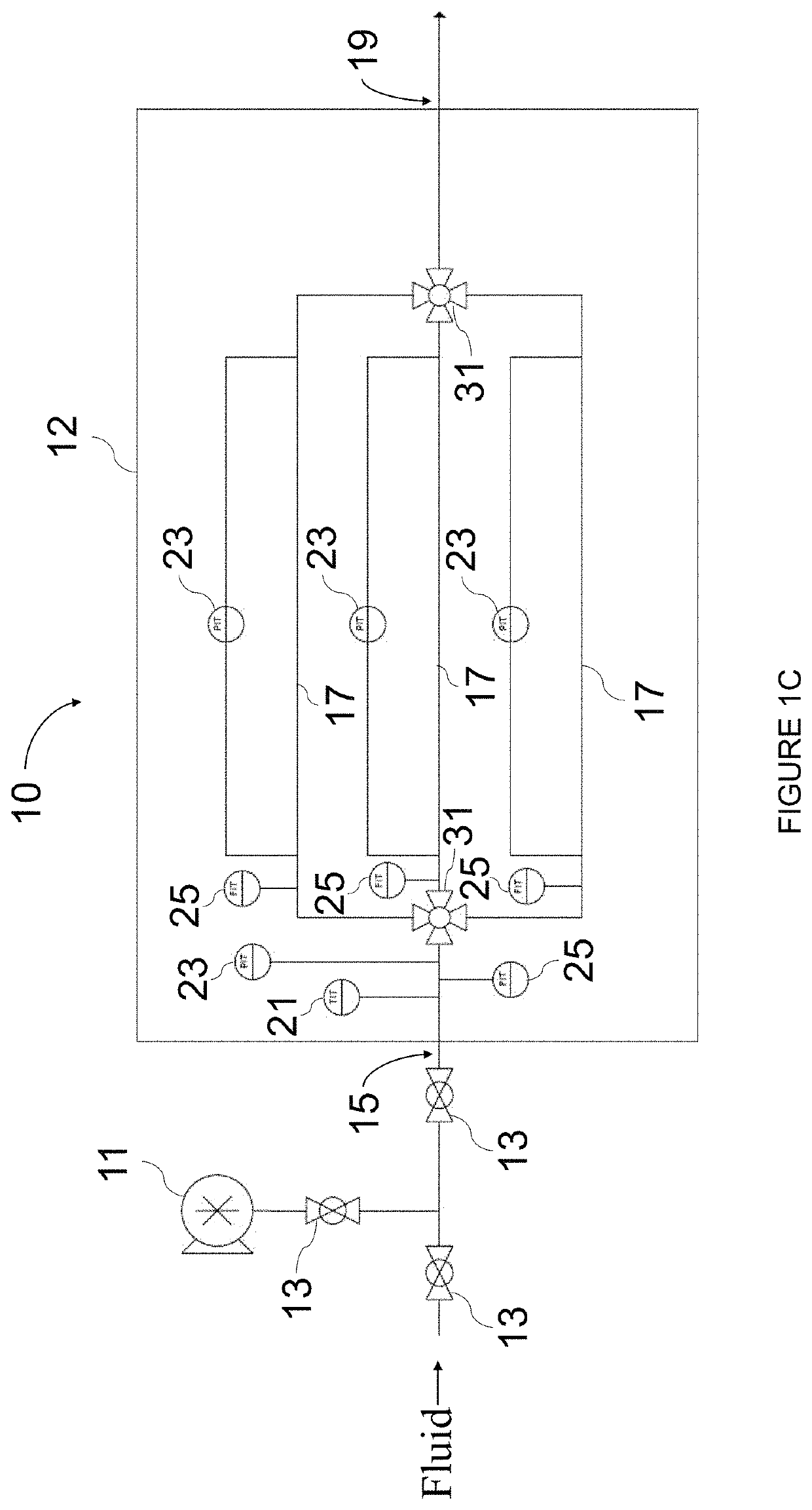
FIELD OF THE INVENTION[0001]The present invention relates generally to systems and processes for improved drag reduction estimation and measurement and more specifically to portable drag reduction analyzers and processes for upscaling drag reduction data for a variety of field applications.BACKGROUND AND SUMMARY[0002]Drag reducing agents also called, among other names, drag reducers or friction reducers are commonly employed in many applications to, for example, reduce frictional pressure loss during fluid flow in a conduit or pipeline in a variety of applications. A few common applications include, for example, hydraulic fracturing, pipelines, injecting fluid, produced water, water transportation, disposal wells, irrigation or other well systems, and the like. There are a wide variety of drag reducing agents that include, for example, various polymers, fibers, surfactants, and boosters.[0003]Unfortunately, current testing procedures of drag reducing properties of various agents req...

Claims


Application Information

Patent Timeline
Patent Type & Authority Patents(United States)
IPC IPC(8): E21B21/08G01N11/04E21B43/267
CPCE21B21/08E21B43/267G01N11/04G01N11/08E21B43/2607
Inventor NIZAMIDIN, NABIJANLINNEMEYER, HAROLD
Owner CHEVROU USA INC
Learn More