Safety circuits for electric heating element

a safety circuit and heating element technology, applied in the direction of therapeutic cooling, program control, instruments, etc., can solve problems such as potential safety problems

Active Publication Date: 2021-08-10
FAN YU HEALTH TECH BUSINESS CO LTD
View PDF6 Cites 0 Cited by
  • Summary
  • Abstract
  • Description
  • Claims
  • Application Information

AI Technical Summary

Benefits of technology

[0001]This disclosure describes circuits and associated software algorithms that help prevent safety-related th...

Problems solved by technology

Electronically-controlled products such as heating pads, heating wraps, heating blankets and the like that use household electricity as th...

Method used


Image

  • Safety circuits for electric heating element
  • Safety circuits for electric heating element
  • Safety circuits for electric heating element

Examples


Embodiment Construction

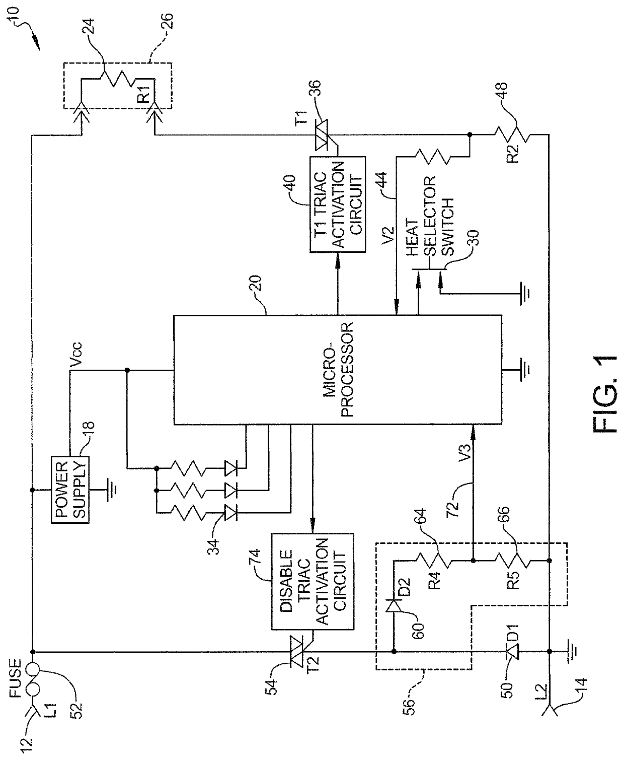
[0017]An example of a safety system constructed in accordance with this disclosure is shown in FIG. 1. This system can be used with any type of electrical load such as electrically-powered products which generate heat. In the example of FIG. 1, the safety system outlined above is applied to a heating system such as the resistive heating system 10. A power source, such as household alternating current is provided through power lines 12 and 14 to power the heating system 10.

[0018]A power supply 18 provides direct current to a processor such as microprocessor 20. Microprocessor 20 controls the operation of the heating system 10, including the operation and testing of the safety circuits described below.

[0019]AC power is applied to a resistive load such as a resistive heating element 24 to provide heat to a heating product such as a heating pad 26. The heating element 24 can take the form of a resistive heating wire R1. A user selects a desired level of heat by operating a heat selector...


PUM


Abstract

A system controller such as a microprocessor receives voltage signals produced from a resistor identifying the functional or nonfunctional operating state of a power switch which controls the amount of power provided to a load in an electrical system. The resistor is also used to provide voltage signals representing the temperature of a heating element of the type used in heating pads and heating blankets. The functional or nonfunctional operating state of a safety switch in a safety circuit capable of blowing a fuse and cutting power to the load is periodically tested to ensure the safety of the electrical system.

Description

BACKGROUND AND SUMMARY[0001]This disclosure describes circuits and associated software algorithms that help prevent safety-related thermal events such as overheating in electrically-heated products and particularly in heated pads and heated blankets.[0002]Electronically-controlled products such as heating pads, heating wraps, heating blankets and the like that use household electricity as the source of power utilize an electronic power switch or “main power switch” that applies electric power to loads posing potential safety issues. Such loads include heating elements such as heating wires provided within heating pads and heating blankets.[0003]In the case of electrically-heated products, the power is provided on an as needed basis and as directed by a microprocessor to maintain desired temperatures selected by a user. The main power switch turns on and off at varying intervals to produce and maintain a temperature level selected by a user. In practical terms, an electronic power sw...

Claims


Application Information

Patent Timeline
IPC IPC(8): G05B19/042H05B1/02
CPCH05B1/02G05B19/042G05B2219/25252H05B1/0272A61F7/007A61F2007/0071A61F2007/0096A61F2007/0093A61F7/0097
Inventor KOHN, GABRIEL S.
Owner FAN YU HEALTH TECH BUSINESS CO LTD
Why Eureka
Try Eureka