Vehicle movement control device

a technology of vehicle movement and control device, which is applied in the direction of vehicle position/course/altitude control, process and machine control, instruments, etc., can solve problems such as inability to cope, and achieve the effect of stable vehicle behavior

Active Publication Date: 2021-08-17
HITACHI ASTEMO LTD
View PDF13 Cites 2 Cited by
  • Summary
  • Abstract
  • Description
  • Claims
  • Application Information

AI Technical Summary

Benefits of technology

[0011]The present invention achieves a vehicle movement control device which reduces a peak value of a resultant acceleration of longitudinal and lateral accelerations, for stable vehicle behavior. Problems, configurations, and effects other than those in the above description will be made clear in the following descriptions of the embodiments.

Problems solved by technology

The LKS is used to keep a lane, that is, to travel on a preset path, and cannot cope with a case where it is necessary to change the travel path.

Method used


Image

  • Vehicle movement control device
  • Vehicle movement control device
  • Vehicle movement control device

Examples


first embodiment

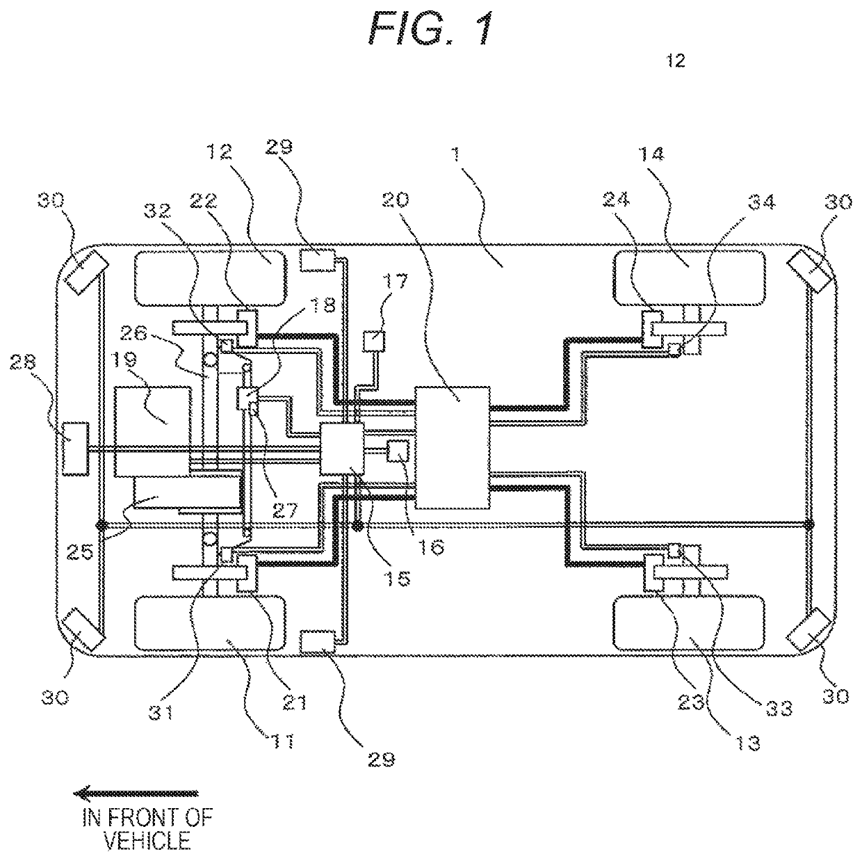
[0031]FIG. 1 is a configuration diagram of a vehicle 1 in which an automatic driving system according to a first embodiment is mounted. The term “automatic driving system” used herein represents a mode in which the system may simultaneously control steering and acceleration / deceleration. For example, the automatic driving system represents an automatic lane change system triggered by a driver's instruction, an automatic braking and steering avoidance system used only in an emergency, and a fully automatic driving system without bothering a driver. The vehicle 1 is configured to control steering and acceleration / deceleration on the basis of a control command from a vehicle movement control device 15 without depending on the driver's operation.

[0032]A steering device 18 includes an electric power steering (EPS). In addition to the function of the power steering for amplifying the driver's steering force, the EPS has a function of receiving a control command transmitted from the vehicl...

second embodiment

[0092]According to the first embodiment, it is necessary to search for the target path online. According to the second embodiment of the present invention, a procedure for calculating the target path by referring to a correspondence relationship mapped in advance on the basis of offline calculation will be described. The other configurations are the same as those in the first embodiment.

[0093]The present invention is directed to the vehicle movement in the lane changing mode, and the number of input parameters necessary for defining the steering profile is limited. Therefore, in the second embodiment, the final lateral position and yaw angle for the steering profile are obtained by referring to the map previously prepared.

[0094]More specifically, for example, a plurality of patterns of combinations of four parameters of the avoidance distance, the lateral movement amount, and the vehicle speeds at the start point and end point of the lane change path are set by using discrete values...

third embodiment

[0100]The travel path described in the above embodiments may be combined with dynamic path generation other than the lane changing mode. In Embodiment 3 according to the present invention, an example of the combination will be described.

[0101]When the end point of the lane change path set according to the present invention is on the predetermined travel path, lane change control is finished when the lane change reaches the end point, and travel control following the predetermined path is restored. When the end point of the lane change path set according to the present invention is not on the predetermined travel path, it is necessary to generate a path in front of the lane change path. In this case, the vehicle movement control device 15 determines again whether traveling in the lane changing mode is necessary, on the basis of the surrounding situations. At this time, when returning to the predetermined path by using the travel path in the lane changing mode, the end point of the la...


PUM


Abstract

The present invention provides a vehicle movement control device which is capable of achieving stable vehicle behavior during the movement of a vehicle in lane changing mode. When calculating a travel path for turning a vehicle to the left side or the right side and then turning the vehicle to the other side, this vehicle movement control device calculates the travel path so that the peak value of the curvature of the travel path decreases in a section where the vehicle speed is higher.

Description

CROSS-REFERENCE TO RELATED APPLICATIONS[0001]This application is a National Phase of International Patent Application No. PCT / JP2017 / 027611 filed on Jul. 31, 2017, which claims priority to Japanese Patent Application No. 2016-185433 filed on Sep. 23, 2016. The contents of these applications are herein incorporated by reference in their entirety.TECHNICAL FIELD[0002]The present invention relates to a vehicle movement control device for controlling the movement of a vehicle.BACKGROUND ART[0003]In recent years, advanced driving assistant system (hereinafter referred to as ADAS) and automatic driving related technologies have been developed rapidly in automobiles.[0004]The technology of partially automating driving operation can be classified into controlling the longitudinal movement of a vehicle and controlling the lateral movement thereof. Examples of controlling the longitudinal movement include adaptive cruise control (ACC), an automatic emergency brake (AEB), and the like. The ACC...

Claims


Application Information

Patent Timeline
Patent Type & Authority Patents(United States)
IPC IPC(8): G05D1/02B60W10/04B60W10/20B62D15/02B62D6/00B60W10/06B60W30/02B60W30/09B60W40/11B60W10/08B60W30/10B60W30/095B60W40/114
CPCG05D1/0223B60W10/04B60W10/06B60W10/08B60W10/20B60W30/02B60W30/095B60W30/10B60W40/114B62D6/003B62D15/0255B60W30/09B60W2520/125B60W2710/06B60W2710/205B60W2710/207B60W2720/10G05D1/0212G05D2201/0213B60W30/0956B60W30/18163
Inventor AKIYAMA, YUKITAKAHASHI, JUNYAINNAMI, TOSHIYUKI
Owner HITACHI ASTEMO LTD
Why Eureka
Try Eureka